26 D-303222 PowerMaster-10 / PowerMaster-30 Installer's Guide
2.3.9 Optional Expander Module Mounting
The Expander module enables connection of speech box, site external siren, site internal siren or strobe and
connection of wired detector to zone number 29 and 30
∗
.
The Expander module also enables connection of a desired device to PGM (programmable) output that is
activated according to predefined conditions.
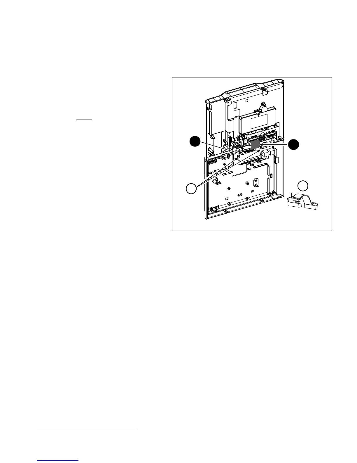
Mount the Expander module as shown in Figure 3.20.
1. Press downward on the Expander module
(located in the back panel) between its 2 clips.
2. Connect the Expander module flat cable to the
front panel Expander receptacle.
Caution! The receptacle with strain relief clip is for
the front unit – do not connect it to the e back unit!
A. 2 clips
B. Strain relief clip
2
1
A
B
Figure 3.20 –Expander Module Mounting
∗
Wired zones 29 and 30 can be enrolled in any two zones in the PowerMaster-30 control panel from 01 to 64