4-40 BA 357-00 * 3.0 * 35700_04_Inbetriebnahme_03.fm
4 Putting into operation
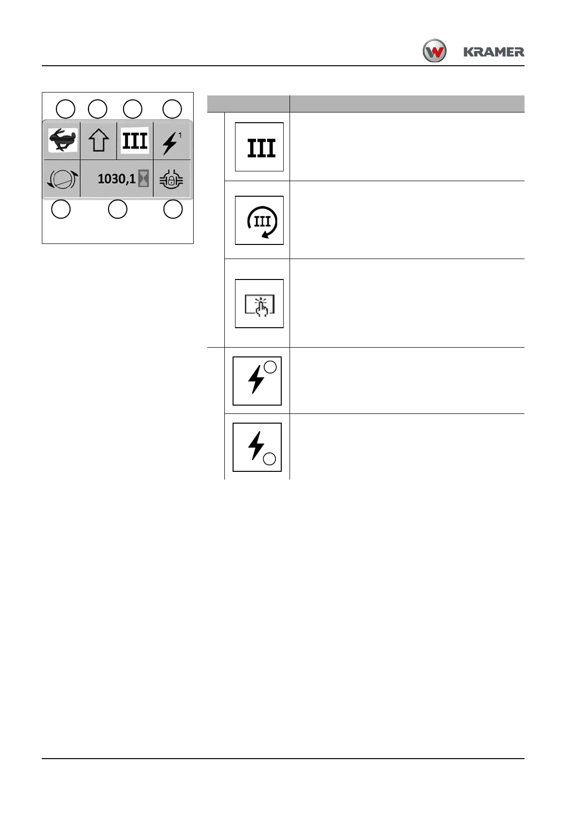
Indication Meaning
C
Indicator display – 3rd control circuit in jog mode
Illuminates if the 3rd control circuit is enabled
– see chapter 5 “Operation of 3rd control circuit” on
page 5-42.
Indicator display – 3rd control circuit
in continuous operation
Illuminates if the 3rd control circuit is enabled in
continuous operation
– see chapter 5 “Continuous operation of 3rd control
circuit” on page 5-44.
Warning indicator– Error "STOP"
Illuminates if the machine electronics
report a critical error during operation.
➥ An error message is displayed in the digital
display 45 in area F as error code.
➥ The warning light 39 illuminates.
D
Indicator display – front socket (opt)
Illuminates if the 1st control circuit of the front socket
was enabled
– see chapter 5 “Electric connection – 7-pole front
socket (opt)” on page 5-106.
Indicator display – front socket (opt)
Illuminates if the 2nd control circuit of the front socket
was enabled
– see chapter 5 “Electric connection – 7-pole front
socket (opt)” on page 5-106.