4 Putting into operation
4-30 BA 357-00 * 3.0 * 35700_04_Inbetriebnahme_02_a3.fm
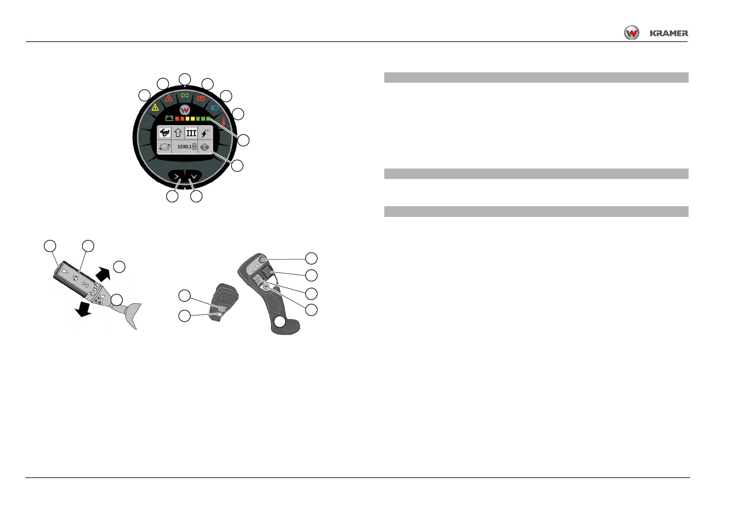
Indicating instrument, joystick, multifunctional lever
Display instrument For more information see page
38 Warning light (yellow) – error warning ECU ............................................................................................ 4-34
39 Warning light (red) – error "STOP"...........................................................................................................4-34
40 Indicator light (green) – right/left-hand turn indicators..............................................................................5-21
41 Warning light (red) – parking brake........................................................................................................... 5-6
42 Indicator light (blue) – high beam.............................................................................................................5-20
43 Warning light (red) – temperature ............................................................................................................4-35
44 Indicator display battery charge condition ...............................................................................................4-36
45 Digital display ...........................................................................................................................................4-37
46 Push button for menu navigation in the digital display4-37
47 Push button for menu navigation in the digital display4-37
Multifunctional lever turn indicators, windshield wipers, horn. For more information see page.
48 Push button – (signal horn) ......................................................................................................................5-25
49 Rotary switch and push button – front wiper, washer pump
1
...................................................................5-26
1. only in the cabin cpl. (opt)
50 Control lever – turn indicator ....................................................................................................................5-21
Control lever (joystick) For more information see page
51 Push button – differential lock ..................................................................................................................5-16
52 Switch – operation of 3rd control circuit, for example locking and unlocking the quickhitch ....................5-42
53 ON/OFF push button – power supply front socket .................................................................................5-106
54 Switch – without function (included for future development stages)
55 Switch – forward/reverse travel direction .................................................................................................5-13
56 Push button – travel direction in neutral...................................................................................................5-13
44
38
39
40
41
42
43
45
48 49
35
51
52
9
54
55
56
53
Fig. 78
R
L
50
4647