Sound Parameters – Filter Introduction
Waldorf microQ User´s Manual 72
Filter Introduction
Once the audio signal leaves the mixer, it is sent to the filters. The microQ has two independent filter
units, each with its own individual settings. The signal flow in the filters can be controlled via the
Routing function. The filters are components that have significant influence on the microQ’s sound
characteristics.
For a detailed description of the different filter types that are available in the microQ, see the section
“Filter Types” on page 78. For now, we’ll explain the basic function of a filter discussing the type used
most commonly in synthesizers: the low pass filter.
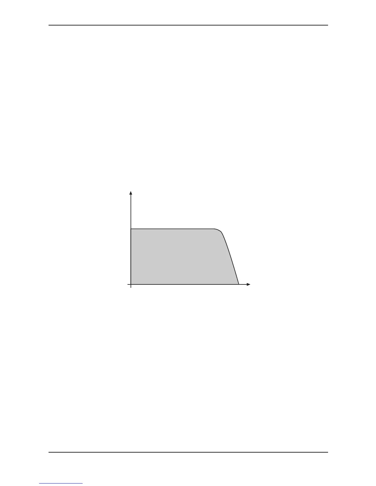
The low pass filter type dampens frequencies that lie above a specified cutoff frequency. Frequencies
below this threshold are hardly affected. The frequency below the cutoff point is called the pass band
range, the frequencies above are called the stop band range. The microQ’s filter dampens frequencies
in the stop band with a certain slope. The slope can be 12dB or 24dB per octave. This means that the
level of a frequency that lies an octave above the cutoff point will be 12dB or 24dB less than those
frequencies of the signal that fall into the pass band. The following picture shows the basic principle
of a low pass filter:
Frequency
Level
Cutoff
Picture 18: Low Pass Filter principle
To give you an idea of the extent of damping, consider this example of a low pass filter: A reduction
of 24dB reduces the original level one octave above the cutoff point by approx. 94%. The damping
factor two octaves above the cutoff point reduces the original level by more than 99%, which in most
cases means this portion of the signal is no longer audible.
The microQ’s filter also features a resonance parameter. Resonance in the context of a low, band or
high pass filter means that a narrow frequency band around the cutoff point is emphasized. The
following picture shows the effect of the resonance parameter on the filter’s frequency curve:
 Loading...