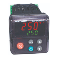
Watlow EZ-ZONE
®
PMI Controller • 189 • Chapter 9 Features
You can create a scale range representing other units for special applications. You can re-
verse scales from high values to low values for analog input signals that have a reversed ac-
tion. For example, if 50 psi causes a 4 mA signal and 10 psi causes a 20 mA signal.
Scale low and high low values do not have to match the bounds of the measurement range.
These along with range low and high provide for process scaling and can include values not
measurable by the controller. Regardless of scaling values, the measured value will be con-
strained by the electrical measurements of the hardware. Select the low and high values
with Scale Low s.Lo and Scale High s.hi. Select the displayed range with Range Low r.Lo
and Range High r.hi (Setup Page, Analog Input Menu).
Range High and Range Low
With a process input, you must choose a value to represent the low and high ends of the
current or voltage range. Choosing these values allows the controller’s display to be scaled
into the actual working units of measurement. For example, the analog input from a humid-
ity transmitter could represent 0 to 100 percent relative humidity as a process signal of 4 to
20 mA. Low scale would be set to 0 to represent 4 mA and high scale set to 100 to represent
20 mA. The indication on the display would then represent percent humidity and range from
0 to 100 percent with an input of 4 to 20 mA. Select the low and high values with Range Low
r.Lo and Range High r.hi (Setup Page, Analog Input Menu).
Receiving a Remote Set Point
The remote set point feature allows the controller to use a thermocouple, RTD, 1 k potenti-
ometer or process signal at input 2 to establish the set point, which allows its set point to be
manipulated by an external source. A common application would use one ramping controller
with a set-point retransmit output to ramp multiple controllers using the remote set point.
Or you could use an analog output from a PLC to send set point values to an EZ-ZONE PM.
The controller must have two process inputs to use the remote set point feature.
You may select between local and remote set points at the front panel, with an event input,
from a remote computer using the communications feature or from an external switch using
an event input. Make sure all input and output impedances are compatible.
1. Switch to the Remote Set Point with Remote Enable r.En (Operations Page, Loop Menu).
Select whether the remote set point controls Manual Power or Set Point with Remote Set
Point Type r.ty.
2. Assign the function of switching to a remote set point to a digital input with Digital Input
Function fn (Setup Page, Digital Input Menu).
3. Assign the function of switching to a remote set point to the EZ Key with Digital Input
Function fn (Setup Page, Function Key Menu).

 Loading...

