Watlow PM PLUS™ 6 • 129 • Chapter 10 Appendix
PM PLUS™ Integrated PID Configuration Options
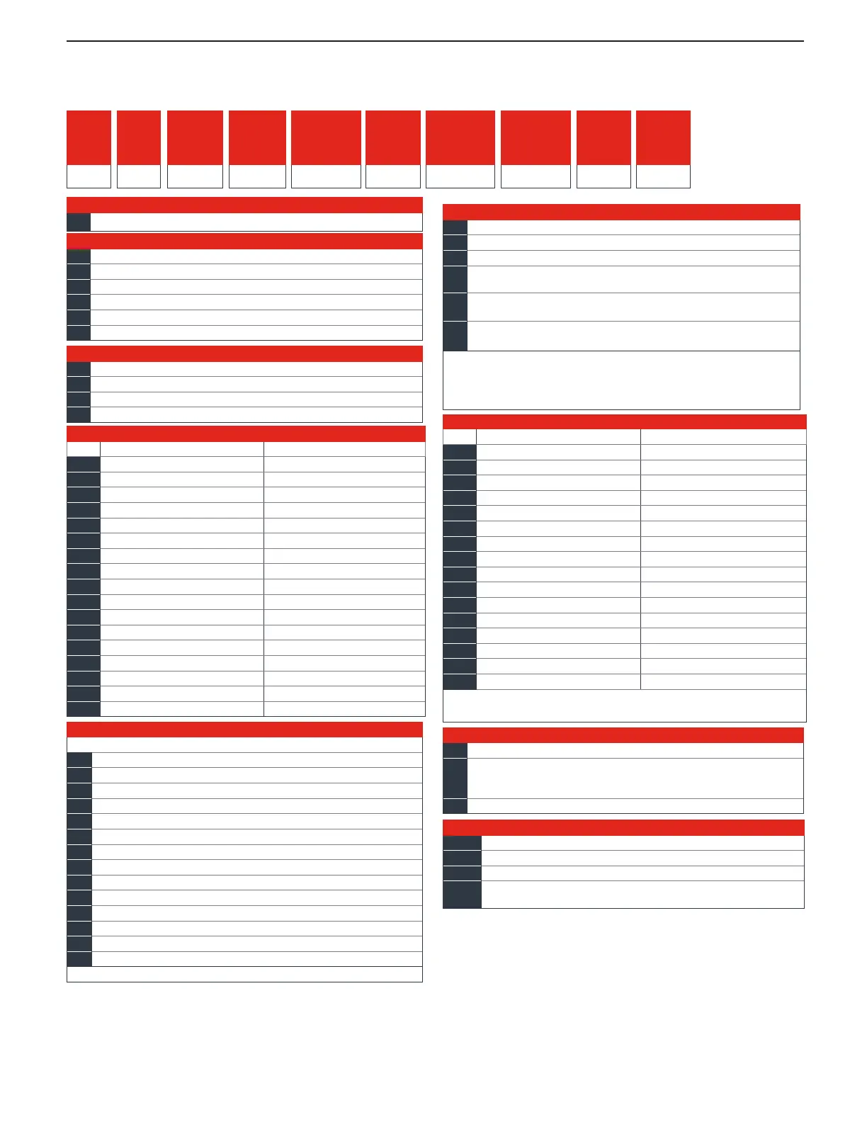
PM PLUS Integrated PID Controller Configuration Code
⑩ ⑪
Output 3 and
4 Hardware
Options
① ②
PM
③
Package
Size
6
④
Primary
Functions
⑤
Power
Supply
Digital I/O
⑥ ⑦
Output 1 and
2 Hardware
Options
⑨
Auxiliary
Control
Functions
⑫
Model
Selection
⑬ ⑭
Custom
Options
③
Package Size
6 =
1
/
16
DIN
④
Primary Functions
C = PID controller with universal input
R = PID controller with universal input and profiling ramp/soak
T = PID controller with universal input and countdown timer
J = PID controller with thermistor input
N = PID controller with thermistor input and profiling ramp/soak
S = Custom firmware
⑤
Power Supply, Digital Inputs/Outputs (I/O)
1 = 100 to 240VAC
2 = 100 to 240VAC plus 2 digital I/O points
3 = 20 to 28VAC or 12 to 40VDC
4 = 20 to 28VAC or 12 to 40VDC, plus 2 digital I/O points
⑥
Output 1 and 2 Hardware Options
Output 1 Output 2
CA =
S
witched dc/open collector None
CH =
Switched dc/open collector NO-ARC 15A power control
CC =
Switched dc/open collector Switched dc
CJ =
Switched dc/open collector Mechanical relay 5A, Form A
CK =
Switched dc/open collector SSR Form A, 0.5A
EA =
Mechanical relay 5A, Form C None
EH =
Mechanical relay 5A, Form C NO-ARC 15A power control
EC =
Mechanical relay 5A, Form C Switched dc
EJ =
Mechanical relay 5A, Form C Mechanical relay 5A, Form A
EK =
Mechanical relay 5A, Form C SSR Form A, 0.5A
FA =
Universal process None
FC =
Universal process Switched dc
FJ =
Universal process Mechanical relay 5A, Form A
FK =
Universal process SSR Form A, 0.5A
AK =
None SSR Form A, 0.5A
KH =
SSR Form A, 0.5A NO-ARC 15A power control
KK =
SSR Form A, 0.5A
S
SR Form A, 0.5A
⑦
⑧
Communication Options
Standard bus always included
A =
None
B =
Bluetooth® (
1
/
16
DIN models only)*
E =
EIA 485 Modbus® RTU and Bluetooth®
F =
Modbus® RTU 232/485 and Bluetooth®
G =
EtherNet/IP™/ Modbus® TCP and Bluetooth®
H =
DeviceNet™ and Bluetooth®
J =
PROFIBUS DP and Bluetooth®
K =
SAE J1939 CAN bus and Bluetooth®
1 =
EIA 485 Modbus® RTU
2 =
EIA 232/485 Modbus® RTU
3 =
EtherNet/IP™/Modbus® TCP
5 =
DeviceNet™
6 =
PROFIBUS DP
7 =
SAE J1939 CAN bus
*Note: Bluetooth® not available in all countries, contact factory.
⑬
Custom Options
WP =
Watlow PM PLUS face plate
WN =
Watlow PM PLUS face plate no logo/no name
AG =
Conformal coating
12 =
Class 1, Div. 2 (not available with integrated limit Option “L”
or “M”, or with Output types E, H or J)
⑭
⑫
Model Selection
P = PM PLUS standard (both analog inputs always isolated)
V =
PM PLUS enhanced firmware which includes compressor
control, ratio, differential, square-root, motorized valve control
without feedback (both analog inputs always isolated)
X =
Not an order option. Appears when Express menu selected.
⑨
Auxiliary Control Functions
A = None
R = Auxiliary 2nd input (universal input)
P = Auxiliary 2nd input (thermistor input)
T =
Current transformer input (not valid Output 3 and 4)
selections = FA, FC, FJ and FK)
L =
Integrated limit controller with universal input (only valid
Output 3 and 4 selections = CJ, EJ and AJ)
M
=
Integrated limit controller with thermistor input (only valid
Output 3 and 4 selections = CJ, EJ and AJ)
Note: If communication options F, G, H, J, K or 2 thru 7 is ordered
in previous digit, then Option A must be ordered here.
All Models: Auxiliary input supports remote set point, backup
sensor ratio, differential and wet-bulb/dry-bulb.
⑩
Output 3 and 4 Hardware Options
Output 3 Output 4
AA =
None
None
AJ =
None
Mechanical relay 5A, Form A
AK =
None
SSR Form A, 0.5A
CA =
Switched dc/open collector None
CC =
Switched dc/open collector Switched dc
CJ =
Switched dc/open collector Mechanical relay 5A, Form A
CK =
Switched dc/open collector SSR Form A, 0.5A
EA =
Mechanical relay 5A, Form C None
EC =
Mechanical relay 5A, Form C Switched dc
EJ =
Mechanical relay 5A, Form C Mechanical relay 5A, Form A
EK =
Mechanical relay 5A, Form C SSR Form A, 0.5A
FA =
Universal process None
FC =
Universal process Switched dc
FJ =
Universal process Mechanical relay 5A, Form A
FK =
Universal process SSR Form A, 0.5A
KK =
SSR Form A, 0.5A SSR Form A, 0.5A
Note: If communication options F, G, H, J, K or 2 thru 7 is ordered in
previous digit, then Option AA must be ordered here.
⑪
⑧
Comm.
Options