Watlow PM PLUS™ 6 • 130 • Chapter 10 Appendix
PM PLUS™ PID Configuration Options
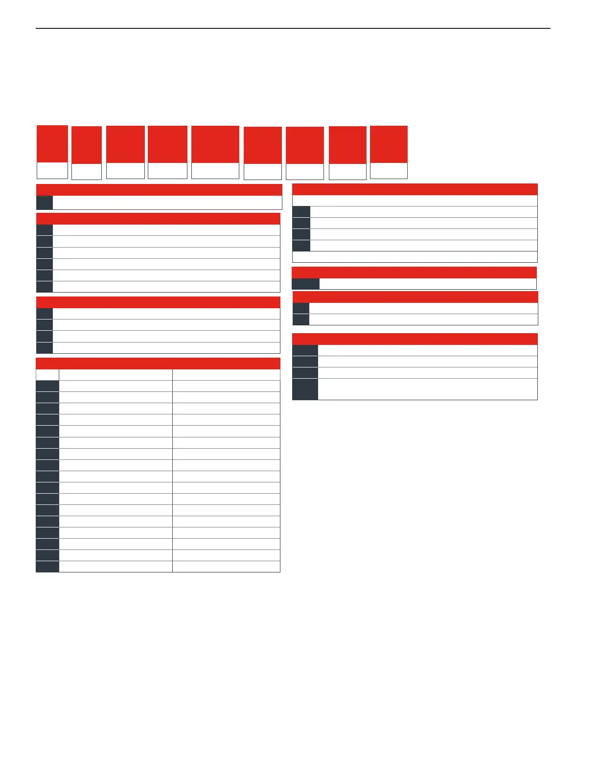
The flexibility of the PM PLUS™ software and hardware allows for a large range of configurations. Below are
the ordering options available. Please refer to the product label on your device to ensure that you understand
the functionality you have available and enabled.
PM PLUS PID Model Configuration Code
⑫
Model
Selection
① ②
PM
③
Package
Size
6
④
Primary
Functions
⑤
Power
Supply
Digital I/O
⑥ ⑦
Output 1 and
2 Hardware
Options
⑧
Comm.
Options
⑨ ⑩ ⑪
Future
Options
A A A
⑬ ⑭
Custom
Options
③
Package Size
6 =
1
/
16
DIN
④
Primary Functions
C = PID controller with universal input
R = PID controller with universal input and profiling ramp/soak
T = PID controller with universal input and countdown timer
J = PID controller with thermistor input
N = PID controller with thermistor input and profiling ramp/soak
S = Custom firmware
⑤
Power Supply, Digital Inputs/Outputs (I/O)
1 = 100 to 240VAC
2 = 100 to 240VAC plus 2 digital I/O points
3 = 20 to 28VAC or 12 to 40VDC
4 = 20 to 28VAC or 12 to 40VDC, plus 2 digital I/O points
⑥
Output 1 and 2 Hardware Options
Output 1 Output 2
CA =
S
witched dc/open collector None
CH =
Switched dc/open collector NO-ARC 15A power control
CC =
Switched dc/open collector Switched dc
CJ =
Switched dc/open collector Mechanical relay 5A, Form A
CK =
Switched dc/open collector SSR Form A, 0.5A
EA =
Mechanical relay 5A, Form C None
EH =
Mechanical relay 5A, Form C NO-ARC 15A power control
EC =
Mechanical relay 5A, Form C Switched dc
EJ =
Mechanical relay 5A, Form C Mechanical relay 5A, Form A
EK =
Mechanical relay 5A, Form C SSR Form A, 0.5A
FA =
Universal process None
FC =
Universal process Switched dc
FJ =
Universal process Mechanical relay 5A, Form A
FK =
Universal process SSR Form A, 0.5A
AK =
None SSR Form A, 0.5A
KH =
SSR Form A, 0.5A NO-ARC 15A power control
KK =
SSR Form A, 0.5A
S
SR Form A, 0.5A
⑦
⑧
Communication Options
Standard bus always included
A =
None
B =
Bluetooth® (
1
/
16
DIN models only)*
E =
EIA 485 Modbus® RTU and Bluetooth®
1 =
EIA 485 Modbus® RTU
*Note: Bluetooth® not available in all countries, contact factory.
⑬
Custom Options
WP =
Watlow PM PLUS face plate
WN =
Watlow PM PLUS face plate no logo/no name
AG =
Conformal coating
12 =
Class 1, Div. 2 (not available with mechanical relay Output
types E, H or J)
⑭
⑨ ⑩
Future Options
AAA = Future Options
⑪
⑫
Model Selection
P = PM PLUS standard (both analog inputs always isolated)
X = Not an order option. Appears when Express menu selected.