Watlow PM PLUS™ 6 • 18 • Chapter 2: Installation
Wiring Notes
Maximum wire size termi-
nation and torque rating:
0.0507 to 3.30 mm2 (30
to 12 AWG) single-wire
termination or two 1.31
mm2 (16 AWG)
0.56 Nm (5.0 in-lb.)
torque
Adjacent terminals may
be labeled differently
depending on the model
number.
Do not connect wires to
unused terminals.
Maintain electrical isola-
tion between analog
input 1, digital input-
outputs, switched dc/
open collector outputs
and process outputs to
prevent ground loops.
This equipment is suit-
able for use in CLASS
I, DIVISION 2, Groups
A, B, C and D or Non-
Hazardous locations only.
Temperature Code T4A
Wiring Warnings
ç
Use National Electric
(NEC) or other country-
specic standard wiring
and safety practices
when wiring this control-
ler to a power source,
electrical sensors or pe-
ripheral devices. Failure
to do so may result in
damage to equipment
and property, and/or in-
jury or loss of life.
Explosion Hazard - Dry
contact closure Digital
Inputs shall not be used
in Class I Division 2 Haz-
ardous Locations unless
switch used is approved
for this application.
Explosion Hazard – Sub-
stitution of component
may impair suitability for
CLASS I, DIVISION 2.
Explosion Hazard - Do
not disconnect while the
circuit is live or unless
the area is known to be
free of ignitable concen-
trations of ammable
substances.
Wiring Your New PM PLUS™
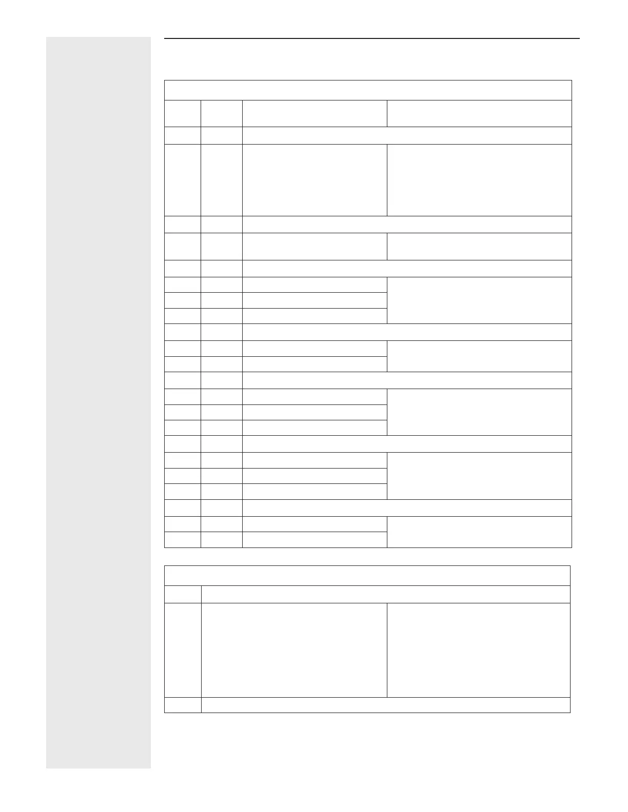
Inputs and Outputs
Input
1
Input
2
Input Function Configuration Code
Slot A Slot B
UNIVERSAL, RTD, THERMISTOR INPUTS
T1
S1
R1
T2
S2
R2
S2 (RTD) or current +
S3 (RTD), thermocouple -, cur-
rent -, potentiometer wiper,
thermistor or volts -
S1 (RTD), thermocouple +, volts
+, potentiometer or thermistor
Input 1: all configurations
Input 2: PM _ _ _ _ _ - _ [R,L] _ _ _ _ _
Slot A Slot B
CURRENT TRANSFORMER INPUT 2
T2
S2
mA ac
mA ac
Input 2: PM _ _ _ _ _ - _ [T] _ _ _ _ _
Slot A Slot B
SWITCHED DC / OPEN COLLECTOR OUTPUTS
X1 X3 common Output 1: PM _ _ _[C] _ - _ _ _ _ _ _ _
Output 3: PM _ _ _ _ _ - _ _ [C] _ _ _ _
W1 W3
DC-
Y1 Y3
DC+
Slot A Slot B
SWITCHED DC OUTPUTS
W2 W4 mA ac Output 2: PM _ _ _ _ [C] - _ _ _ _ _ _ _
Output 4: PM _ _ _ _ _ - _ _ _ [C] _ _ _
Y2 Y4 mA ac
Slot A Slot B
UNIVERSAL PROCESS OUTPUTS
F1 F3 voltage or current - Output 1: PM _ _ _ [F] _ - _ _ _ _ _ _ _
Output 3: PM _ _ _ _ _ - _ _ [F] _ _ _ _
G1 G3 voltage +
H1 H3 current +
Slot A Slot B
MECHANICAL RELAY 5A, FORM C OUTPUTS
L1 L3 normally open Output 1: PM _ _ _ [E] _ - _ _ _ _ _ _ _
Output 3: PM _ _ _ _ _ - _ _ [E] _ _ _ _
K1 K3 common
K1 J3 normally closed
Slot A Slot B
NO-ARC 15A FORM A
L2 L4 normally open Output 2: PM _ _ _ _ [H] - _ _ _ [H*] _ _
_
K2 K4 common
Communications
Slot B
Modbus
®
RTU 232/485 Communications
CB
CA
CC
CB
CA
C5
C3
C2
Modbus
®
RTU EIA-485 T+/R+
Modbus
®
RTU EIA-485 T-/R-
Modbus
®
RTU EIA-485 common
Modbus
®
RTU EIA-485 T+/R+
Modbus
®
RTU EIA-485 T-/R-
Modbus
®
RTU EIA-232 common
Modbus
®
RTU EIA-232 to DB9 pin 2
Modbus
®
RTU EIA-232 to DB9 pin 3
Slot B: PM6 _ _ _ _ - [2] A A A _ _ _
DeviceNet™ Communications