Watlow PM PLUS™ 6 • 19 • Chapter 2: Installation
Wiring Notes
Maximum wire size
termination and torque
rating:
0.0507 to 3.30 mm2 (30
to 12 AWG) single-wire
termination or two 1.31
mm2 (16 AWG)
0.56 Nm (5.0 in-lb.)
torque
Adjacent terminals may
be labeled differently
depending on the model
number.
Do not connect wires to
unused terminals.
Maintain electrical isola-
tion between analog
input 1, digital input-
outputs, switched dc/
open collector outputs
and process outputs to
prevent ground loops.
This equipment is suit-
able for use in CLASS I,
DIVISION 2, Groups A,
B, C and D or Non-Haz-
ardous locations only.
Temperature Code T4A
Wiring Warnings
ç
Use National Electric
(NEC) or other country-
specic standard wiring
and safety practices
when wiring this control-
ler to a power source,
electrical sensors or pe-
ripheral devices. Failure
to do so may result in
damage to equipment
and property, and/or in-
jury or loss of life.
Explosion Hazard - Dry
contact closure Digital
Inputs shall not be used
in Class I Division 2 Haz-
ardous Locations unless
switch used is approved
for this application.
Explosion Hazard – Sub-
stitution of component
may impair suitability for
CLASS I, DIVISION 2.
Explosion Hazard - Do
not disconnect while the
circuit is live or unless
the area is known to be
free of ignitable concen-
trations of ammable
substances.
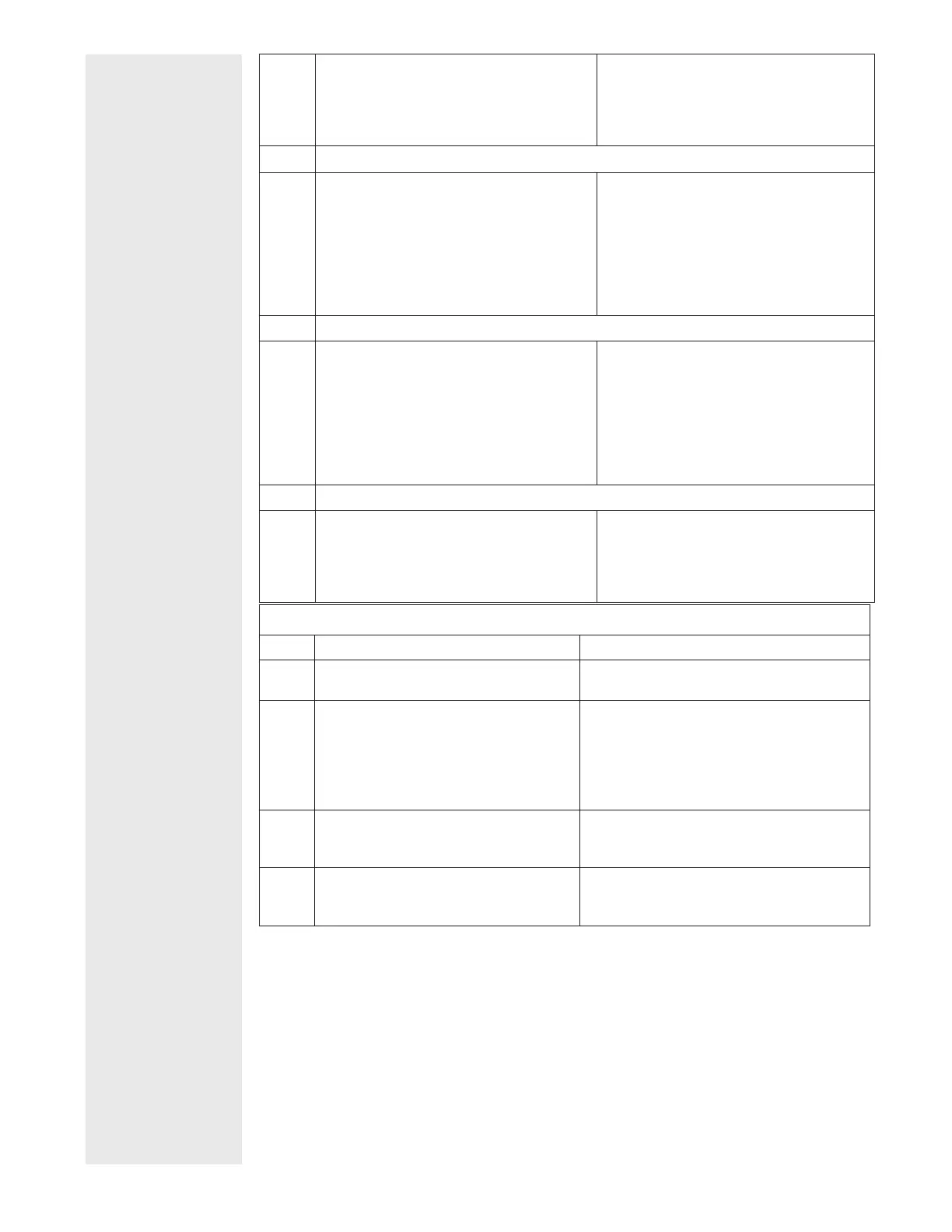
V+
CH
SH
CL
V-
DeviceNet power
Positive side of DeviceNet bus
Shield interconnect
Negative side of DeviceNet bus
DeviceNet power return
Slot B: PM6 _ _ _ _ - [5] A A A _ _ _
EtherNet/IP™ and Modbus
®
TCP
E8
E7
E6
E5
E4
E3
E2
E1
unused
unused
EtherNet/IP and Modbus
®
TCP receive -
unused
unused
EtherNet/IP and Modbus
®
TCP receive +
EtherNet/IP and Modbus
®
TCP transmit -
EtherNet/IP and Modbus
®
TCP transmit +
Slot B: PM6 _ _ _ _ - [3] A A A _ _ _
Profibus DP Communications
VP
B
A
DG
trB
B
A
trA
Voltage Potential
EIA-485 T+/R+
EIA-485 T-/R-
Digital ground (common)
Termination resistor B
EIA-485 T+/R+
EIA-485 T-/R-
Termination resistor A
Slot B: PM6 _ _ _ _ - [6] AAA _ _ _
J1939 CAN bus Communications
CL
CH
SH
V+
V-
Negative side of CAN bus
Positive side of CAN bus
Shield interconnect
CAN bus power
CAN bus power return
Slot B: PM6 _ _ _ _ - [7] A A A _ _ _
Slot C Power or Communications Wiring
Slot C Terminal Function Configuration
98
99
Power input: ac or dc+
Power input: ac or dc-
all
CC
CA
CB
Standard Bus or Modbus
®
RTU EIA-485
common
Standard Bus or Modbus
®
RTU EIA-485
T-/R-
Standard Bus or Modbus
®
RTU EIA-485
T+/R+
PM _ _ _ _ _ - [1] _ _ _ _ _ _
CF
CD
CE
Standard Bus EIA-485 common
Standard Bus EIA-485 T-/R-
Standard Bus EIA-485 T+/R+
PM _ _ _ _ _ - [A,D,2,3,5] _ _ _ _ _ _
B5
D6
D5
Digital input-output common
Digital input or output 6
Digital input or output 5
PM _ _ [2] _ _ - _ _ _ _ _ _ _
PM _ _ [4] _ _ - _ _ _ _ _ _ _