Watlow PM PLUS™ 6 • 23 • Chapter 2: Installation
Wiring Notes
Maximum wire size
termination and torque
rating:
0.0507 to 3.30 mm2 (30
to 12 AWG) single-wire
termination or two 1.31
mm2 (16 AWG)
0.56 Nm (5.0 in-lb.)
torque
Adjacent terminals may
be labeled differently
depending on the model
number.
Do not connect wires to
unused terminals.
Maintain electrical isola-
tion between analog
input 1, digital input-
outputs, switched dc/
open collector outputs
and process outputs to
prevent ground loops.
This equipment is suit-
able for use in CLASS I,
DIVISION 2, Groups A,
B, C and D or Non-Haz-
ardous locations only.
Temperature Code T4A
Wiring Warnings
ç
Use National Electric
(NEC) or other country-
specic standard wiring
and safety practices
when wiring this control-
ler to a power source,
electrical sensors or pe-
ripheral devices. Failure
to do so may result in
damage to equipment
and property, and/or in-
jury or loss of life.
Explosion Hazard - Dry
contact closure Digital
Inputs shall not be used
in Class I Division 2 Haz-
ardous Locations unless
switch used is approved
for this application.
Explosion Hazard – Sub-
stitution of component
may impair suitability for
CLASS I, DIVISION 2.
Explosion Hazard - Do
not disconnect while the
circuit is live or unless
the area is known to be
free of ignitable concen-
trations of ammable
substances.
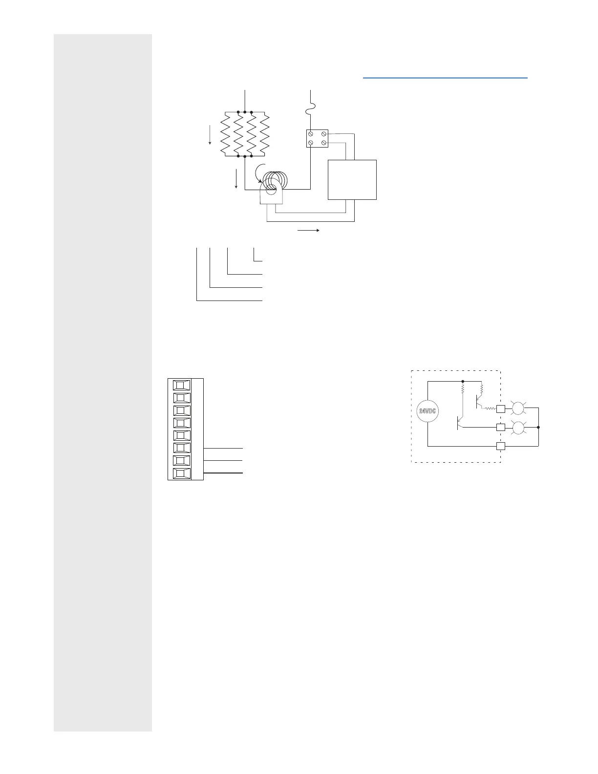
Example Current Transformer:
Digital Output 5 - 6
PM _ _ [2,4] _ _ - _ _ _ _ _ _ _
common
switched dc
switched dc
98
99
CF
CD
CE
B5
D6
D5
Slot C
Digital Output
• SSR drive signal
• Update rate 10 Hz
• Maximum open circuit voltage is
22 to 25V (dc)
• PNP transistor source
• Typical drive; 21mA @ 4.5V (dc)
for DO5, and 11mA @ 4.5V for
DO6
• Current limit 24mA for Output 5
and 12mA Output 6
• Output 5 capable of driving one
3-pole DIN-A-MITE
• Output 6 capable of driving one
1-pole DIN-A-MITE
24VDC
switched dc outputs
Internal Circuitry
D5
D6
B5
Controller
Output N
CT Input
L2 L1
Fuse
SSR
3A x 4
12A
48mA
48mA
x 4 = 48A
Turns around CT
Turns around CT
CT Primary Current
CT Secondary Current
Total current
CT Ratio R = 1000:1
:
CSC = I
p(full scale)
= 50mA(R)/T
CSI = Output N
I
s = Current in secondary of current transformer
Ip = Current in primary of current transformer
T = Number of turns through the primary of the transformer
R = Number of turns in the secondary of the current
transformer (Turns ratio, assuming one primary turn)
CSC = Current Scaling (parameter found in Current Menu
of Setup Page)
CSI = Current Source Instance (parameter found in Curr
Menu of Setup Page)
 Loading...


