Watlow PM PLUS™ 6 • 34 • Chapter 2: Installation
Wiring Notes
Maximum wire size termi-
nation and torque rating:
0.0507 to 3.30 mm2 (30
to 12 AWG) single-wire
termination or two 1.31
mm2 (16 AWG)
0.56 Nm (5.0 in-lb.)
torque
Adjacent terminals may
be labeled differently
depending on the model
number.
Do not connect wires to
unused terminals.
Maintain electrical isola-
tion between analog
input 1, digital input-
outputs, switched dc/
open collector outputs
and process outputs to
prevent ground loops.
This equipment is suit-
able for use in CLASS
I, DIVISION 2, Groups
A, B, C and D or Non-
Hazardous locations only.
Temperature Code T4A
Wiring Warnings
ç
Use National Electric
(NEC) or other country-
specic standard wiring
and safety practices
when wiring this control-
ler to a power source,
electrical sensors or pe-
ripheral devices. Failure
to do so may result in
damage to equipment
and property, and/or in-
jury or loss of life.
Explosion Hazard - Dry
contact closure Digital
Inputs shall not be used
in Class I Division 2 Haz-
ardous Locations unless
switch used is approved
for this application.
Explosion Hazard – Sub-
stitution of component
may impair suitability for
CLASS I, DIVISION 2.
Explosion Hazard - Do
not disconnect while the
circuit is live or unless
the area is known to be
free of ignitable concen-
trations of ammable
substances.
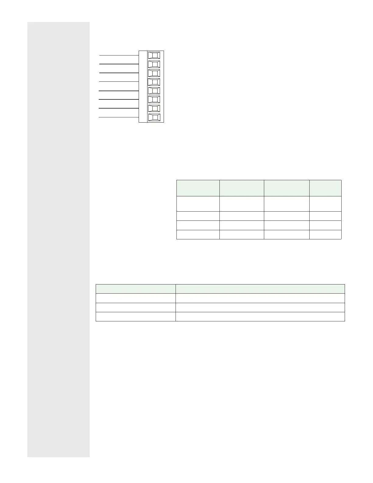
Probus DP Communications
Slot B: PM [6] _ _ _ _-[6] _ _ _ _ _ _
485 T-/R-
+5Vdc Voltage Potential
VP
B
A
DG
trB
B
A
trA
Slot B & E
485 T+/R+
Digital ground
Termination resistor B
485 T+/R+
485 T-/R-
Termination resistor A
• Wire T-/R- to the A terminal of the EIA-485 port.
• Wire T+/R+ to the B terminal of the EIA-485 port.
• Wire Digital Ground to the common terminal of the EIA-485 port.
• Do not route network wires with power wires. Connect network wires
in daisy-chain fashion when connecting multiple devices.
• A termination resistor should be used if this is the last control on the
network.
• If using a 150 Ω cable Watlow provides internal termination. Place a
jumper across pins trB and B and trA and A.
• If external termination is to be used with a 150 Ω cable place a 390 Ω
resistor across pins VP and B, a 220 Ω resistor across pins B and A,
and lastly, place a 390 Ω resistor across pins DG and A.
• Do not connect more than 32 controllers on a segment.
• Maximum EIA-485 network length: 1,200 meters (4,000 feet)
• 1/8th unit load on EIA-485 bus
• When termination jumpers are in place, there is 392 ohm pull up
resistor to 5V and 392 ohm pull down resistor to DG. There is also a
221 ohm resistor between A and B.
• Communications instance 2
Profibus
Terminal
EIA/TIA-485
Name
Watlow Ter-
minal Label
Function
VP (Voltage
Potential)
- - - - VP +5Vdc
B-Line B B T+/R+
A-Line A A T-/R-
DP-GND common DG common
Profibus DP LED Indicators
Viewing the unit from the front and then looking on top of the controller two bi-color
LEDs can be seen where only the front one is used. Definition follows:
Indicator LED Description
Red Profibus network not detected
Red Flashing Indicates that the Profibus card is waiting for data exchange.
Green Data exchange mode