Watlow PM PLUS™ 6 • 37 • Chapter 2: Installation
Wiring Notes
Maximum wire size
termination and torque
rating:
0.0507 to 3.30 mm2 (30
to 12 AWG) single-wire
termination or two 1.31
mm2 (16 AWG)
0.56 Nm (5.0 in-lb.)
torque
Adjacent terminals may
be labeled differently
depending on the model
number.
Do not connect wires to
unused terminals.
Maintain electrical isola-
tion between analog
input 1, digital input-
outputs, switched dc/
open collector outputs
and process outputs to
prevent ground loops.
This equipment is suit-
able for use in CLASS I,
DIVISION 2, Groups A,
B, C and D or Non-Haz-
ardous locations only.
Temperature Code T4A
Wiring Warnings
ç
Use National Electric
(NEC) or other country-
specic standard wiring
and safety practices
when wiring this control-
ler to a power source,
electrical sensors or pe-
ripheral devices. Failure
to do so may result in
damage to equipment
and property, and/or in-
jury or loss of life.
Explosion Hazard - Dry
contact closure Digital
Inputs shall not be used
in Class I Division 2 Haz-
ardous Locations unless
switch used is approved
for this application.
Explosion Hazard – Sub-
stitution of component
may impair suitability for
CLASS I, DIVISION 2.
Explosion Hazard - Do
not disconnect while the
circuit is live or unless
the area is known to be
free of ignitable concen-
trations of ammable
substances.
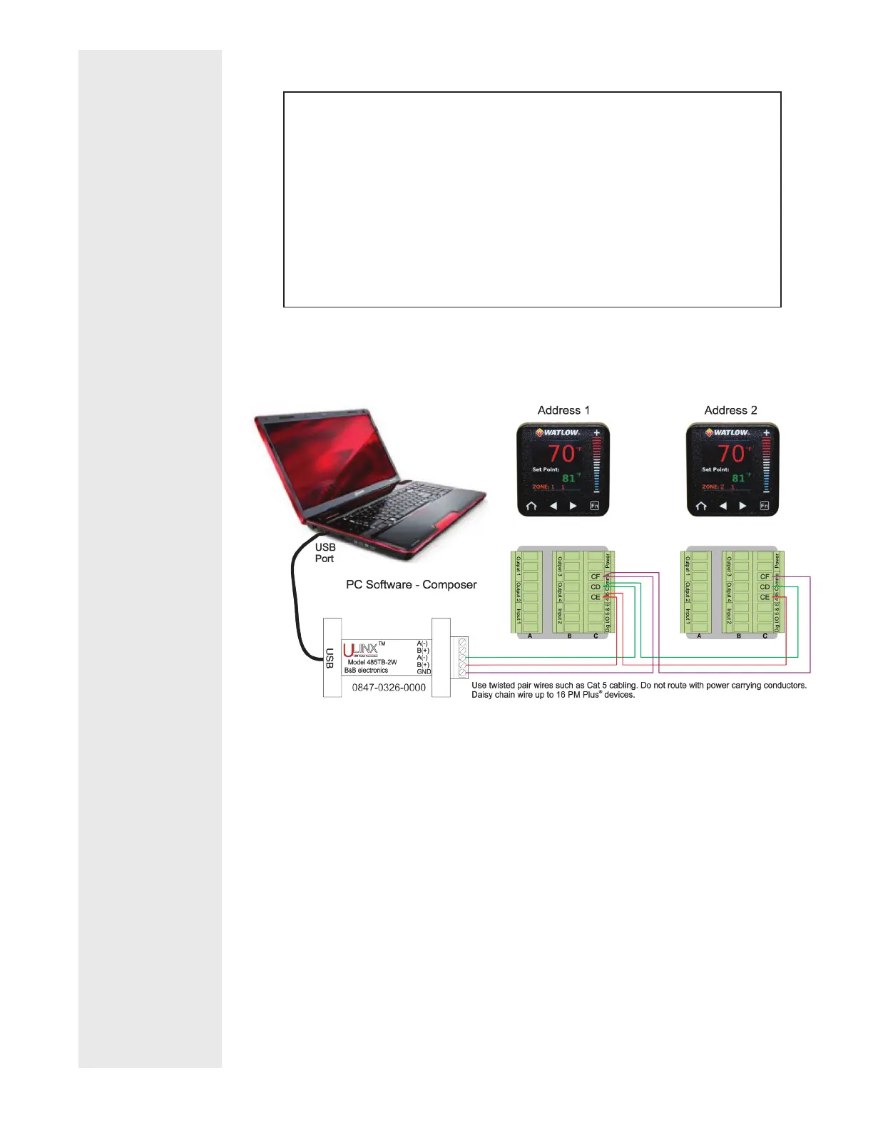
Connecting PM PLUS™ to a PC Using B&B 485 to USB Converter
Do not leave a USB to EIA-485 converter connected to Standard Bus with-
out power (i.e., disconnecting the USB from the computer with the con-
verter connected on Standard Bus).
If you connect a USB converter to your PC we recommend that you change
the Latency Timer from the default 16 msec to 1 msec. Go to Device Man-
ager, double-click Port; right-click the USB serial port; select Properties;
click the Port Settings tab; click the Advanced button, then change the
Latency Timer to 1.
Failure to make this change may cause communication loss between the PC
running EZ-ZONE Configurator and the control.