103
CHAPTER 8 - OPTIONS AND ACCESSORIES
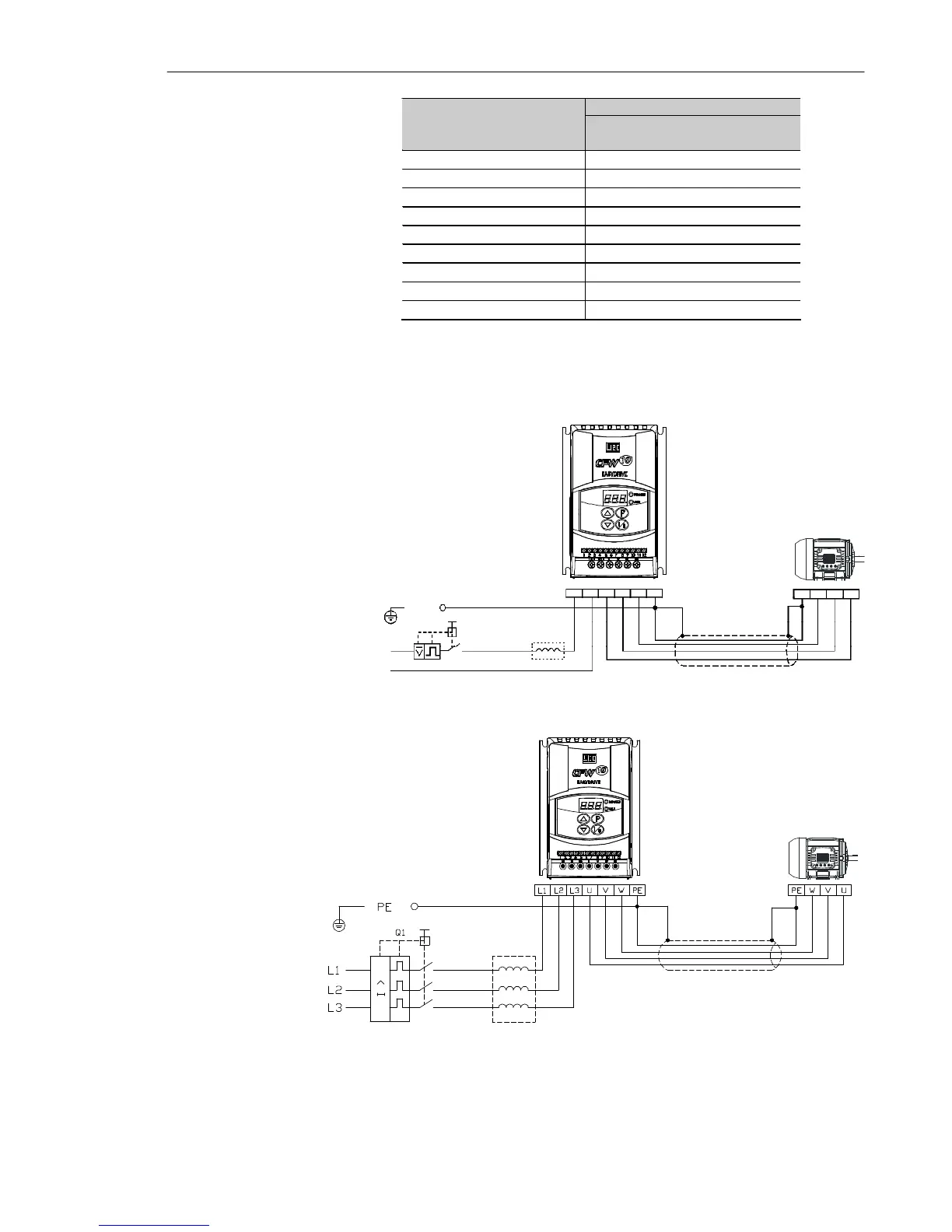
REDE
BLINDAGEM
Table 8.1 - Minimum line impedance for several load conditions
Note: These values ensure a life of 20.000 hour for the DC link capacitors, i.e.,
they can be operated during 5 years with operation of 12 hours per day.
LINE
L/L1
PE
PE UVW
SHIELD
Q1
N/L2
U V W PE
N/L2
L/L1
Minimum Line Impedance
Model
Rated load at inverter output
(I
s
= I
s.nom
)
1.6 A/ 200-240 V 0.5 %
2.6 A / 200-240 V 0.5 %
4.0 A / 200-240 V 0.5 %
7.3 A / 200-240 V 1.0 %
10.0 A / 200-240 V 1.0 %
15.2 A / 200-240 V 2.0 %
1.6 A / 110-127 V 1.0 %
2.6 A / 110-127 V 2.0 %
4.0 A / 110-127 V 1.5 %
a)
b)
Figure 8.2 a) b) - Power connection with line reactor at the input
LINE
SHIELD