36
CHAPTER 3 - INSTALLATION AND CONNECTION
3.2.6 Typical
Terminal
Connections
Connection 1
With the factory default programming, it is posible to operate the
inverter in localmode with the minimum connections shown in figure
3.6 (Power) and without control connections. This operation mode is
recommended for users who are operating the inverter for the first
time as initial learning about equipment. Note that any connection is
needed on control terminal.
For start-up according to this operation mode, refer to Chapter 5.
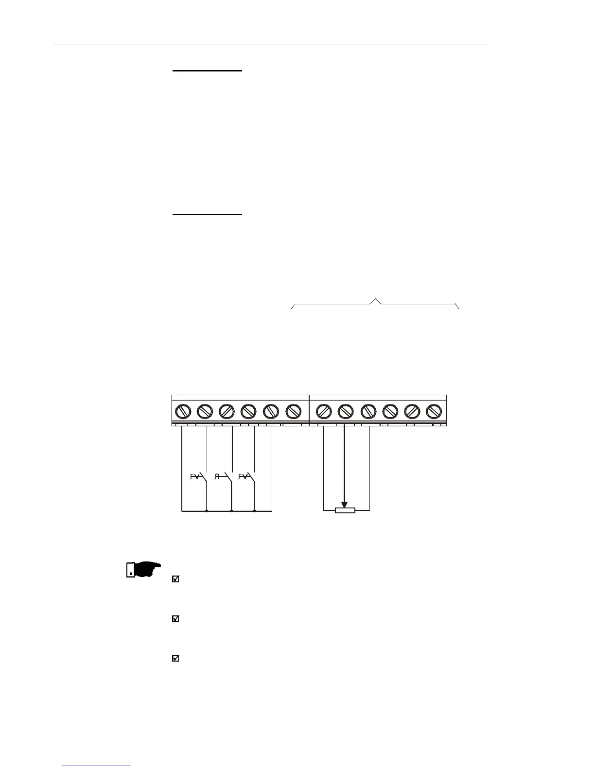
Connection 2
Command enabling via terminals.
S1: FWD/REV
S2: Local/Remote
S3: Start/Stop
R1: Potentiometer for
Speed Setting
Figure 3.10 - Wiring for Connection 2
DI1 - No Function (HMI) or
General Enabling (Terminals)
DI2 - FWD/REV
DI3 - Local/Remote
GND
AI1 (0.4 to 20 mA)
GND
AI1 (0 to 10 Vdc)
+10 V
NC
Common
NO
DI4 - No Function (HMI) or
Start / Stop (Terminals)
S1
1 2 3 4 5 6 7 8 9 10 11 12
5 K
NOTE!
The frequency reference can be sent via AI1 analog input (as shown
in figure above), via keypad HMI-CFW10, or via any other source
(see description of Parameters P221 and P222).
When a line fault occurs by using this type of connection with switch
S3 at position "RUN", the motor will be enabled automatically as
soon as the line is re-established.
Function 2 configuration is not possible on CFW-10 Clean version.
S2 S3
Not available on Clean version