29
CHAPTER 3 - INSTALLATION AND CONNECTION
NOTE!
Cable dimensions indicated in table 3.3 are reference values only.
Installation conditions and the maximum acceptable line voltage drop
shall be considered when sizing the power cables.
Table 3.4 - Recommended tightening torques for power connections
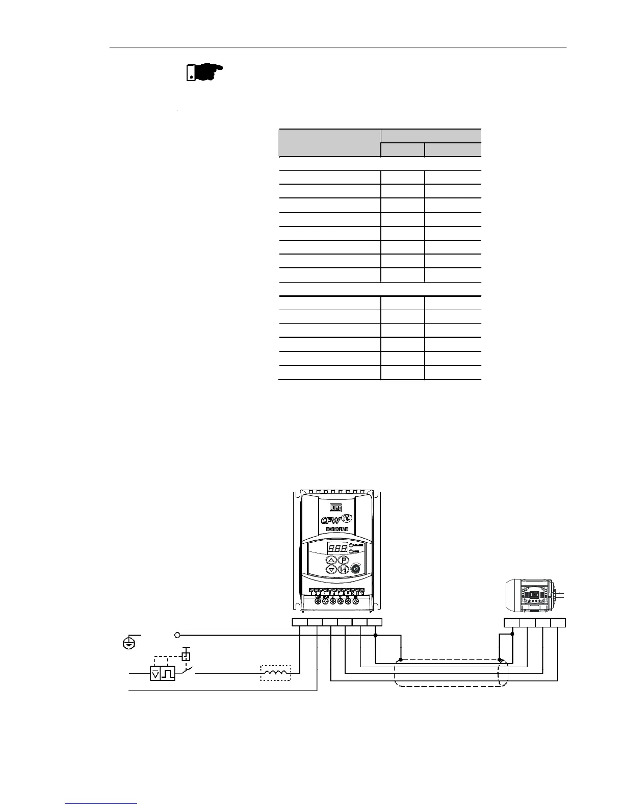
a) Models 1.6 A, 2.6 A and 4.0 A/200-240 V and 1.6 A and 2.6 A/110-127 V (single-phase)
3.2.4 Power Connections
POWER SUPPLY
L/L1
PE
PE UVW
SHIELDING
Q1
N/L2
U V W PE
N/L2
L/L1
Figure3.6 a) - Grounding and power supply connections
Power Cables
Model
N.m Lbf.in
SINGLE-PHASE
1.6 A / 200-240 V 1.0 8.68
2.6 A / 200-240 V 1.0 8.68
4.0 A / 200-240 V 1.0 8.68
7.3 A / 200-240 V 1.76 15.62
10.0 A / 200-240 V 1.76 15.62
1.6 A / 110-127 V 1.0 8.68
2.6 A / 110-127 V 1.0 8.68
4.0 A / 110-127 V 1.76 15.62
THREE-PHASE
1.6 A / 200-240 V 1.0 8.68
2.6 A / 200-240 V 1.0 8.68
4.0 A / 200-240 V 1.0 8.68
7.3 A / 200-240 V 1.0 8.68
10.0 A / 200-240 V 0.5 4.4
15.2 A / 200-240 V 0.5 4.4