34
CHAPTER 3 - INSTALLATION AND CONNECTION
3.2.5 Signal and
Control
Connections
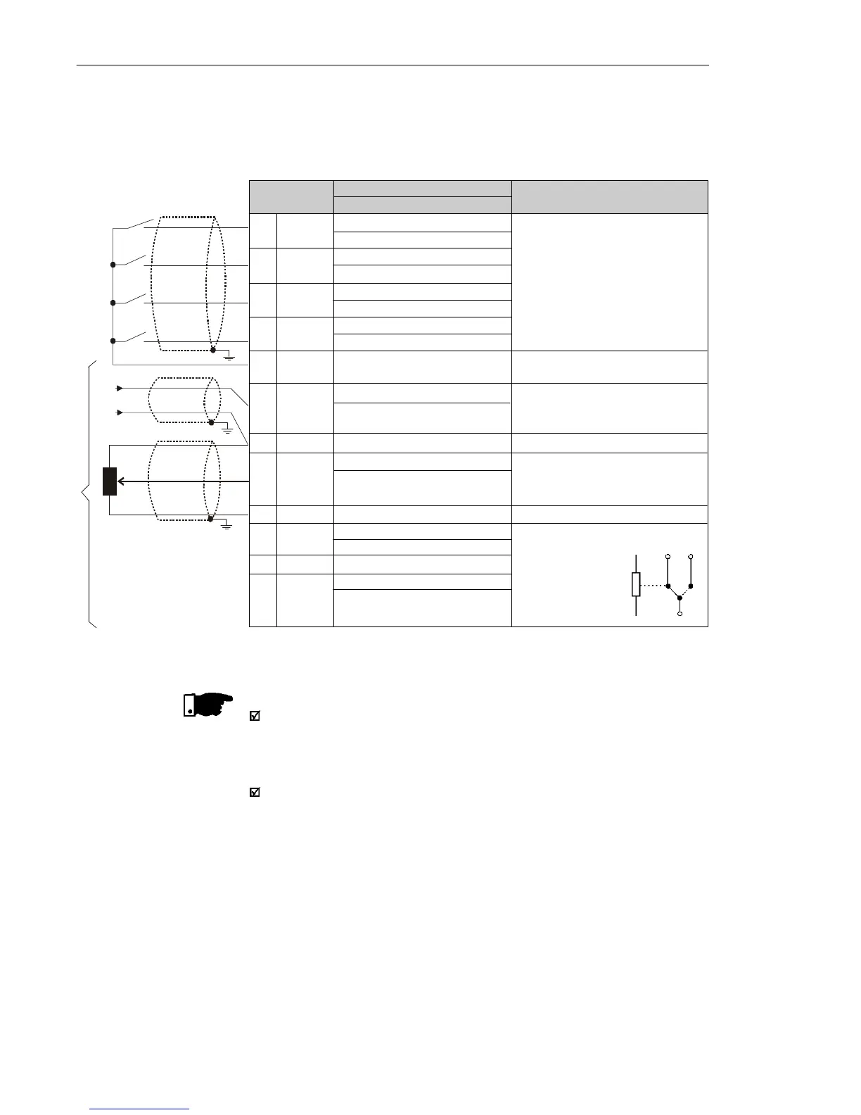
The signal (analog input) and control connections (digital inputs and
relay output) are made on the XC1 connector of control board (see
location in figure 3.5).
Figure 3.8 - Description of the XC1 terminal of the control board
XC1 Terminal
1 DI1
2 DI2
3 DI3
4 DI4
5 GND
6 AI1
7 GND
8 AI1
9 +10 V
10 NC
11 Common
12 NO
Description
Factory Default Function
Digital Input 1
General Enable (remote mode)
Digital Input 2
FWD/REV (remote mode)
Digital Input 3
Local/Remote
Digital Input 4
Start/Stop (remote mode)
0 V Reference
Analog Input 1
Freq. Reference
(remote mode)
0 V Reference
Analog Input (voltage)
Frequency Reference (remote)
Potentiometer Reference
Relay NC Contact
No Fault
Relay Output - common point
Relay NO Contact
No Fault
Specifications
4 isolated digital inputs
Minimum High Level: 10 Vdc
Maximum High Level: 30 Vdc
Maximum Low Level: 3 Vdc
Input current: -11 mA @ 0 Vdc
Max. input current: -20 mA
Not interconnected with PE
Current:(0 to 20) mAor (4to 20) mA
Impedance: 500 Resolution: 7 bits
Not interconnected with PE
Voltage: 0 to 10 Vdc
Impedance:100 k Resolution: 7bits
Max. input voltage: 30 Vdc
+10 Vdc, ± 5 %, capacity: 2 mA
CW
CCW
5k
Contact capacity:
0.5 A / 250 Vac
1.0 A / 125 Vac
2.0 A / 30 Vdc
(+)
(-)
Relay
10 12
11
NOTE!
If the input current from (4 to 20) mA is used as standard, do not
forget to set the Parameter P235 which defines the signal type at
AI1.
The analog input AI1 and the Relay output, (XC1:6…12) are
not available on Clean version of the CFW-10.
(0 to 20) mA
(4 to 20) mA
Not available on Clean version