38
CHAPTER 3 - INSTALLATION AND CONNECTION
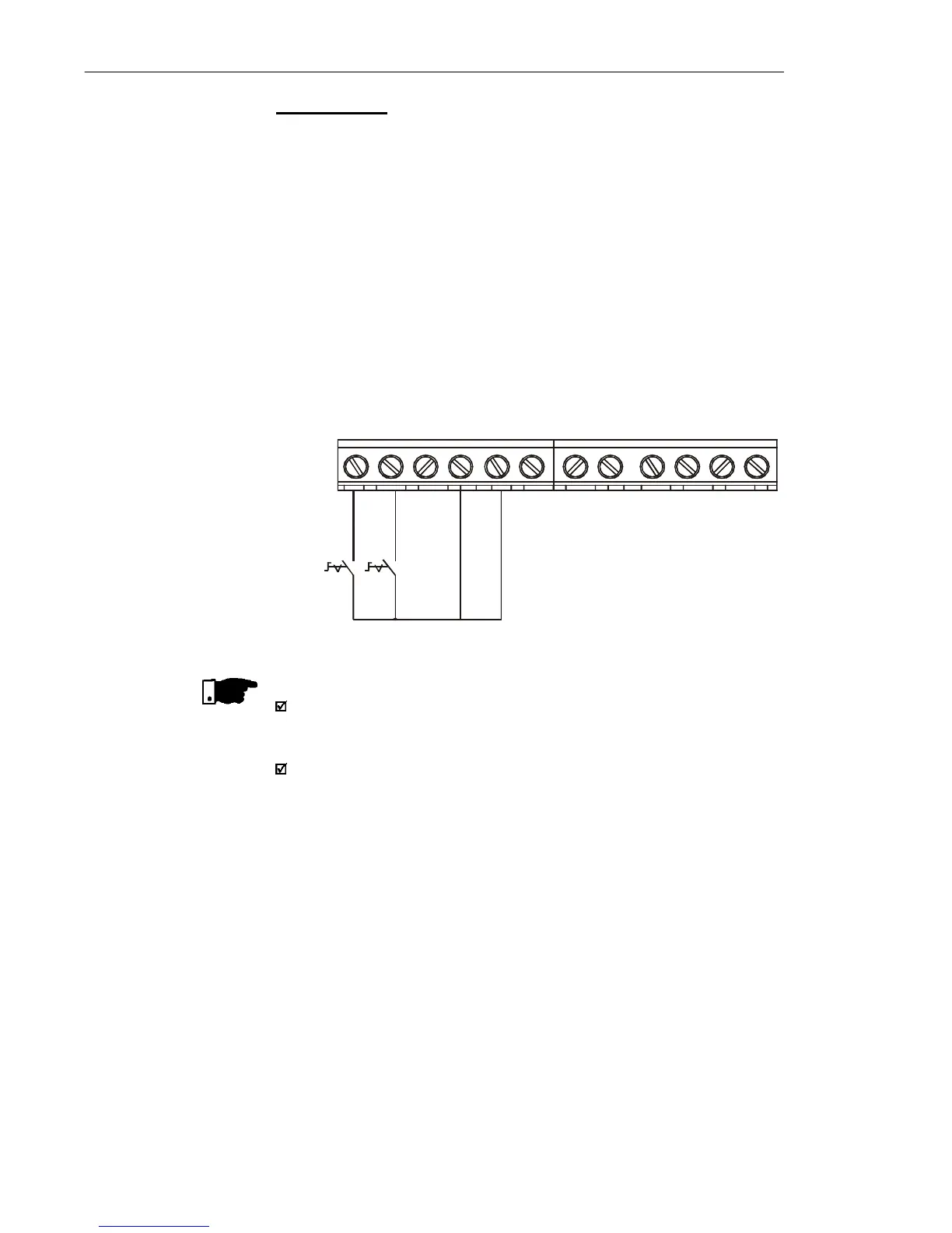
Connection 4
Enabling of the FWD/REV function:
Set DI1 to Forward Run : P263 = 9
Set DI2 to Reverse Run: P264 = 10
Make sure the inverter commands are via terminals, i.e., set
P229 = 1 to local mode.
NOTE!
The speed reference can be realized via Analog Input AI1 (as in
connection 2), via keypad (HMI), or via any other source (see
description of parameters P221 and P222).
When a line fault occurs in this connection mode with switch S1 or
switch S2 is closed, the motor will be enabled automatically as
soon as the line is re-restablished.
Figure 3.12 - Wiring for Connection 4
DI4 - No Function / Ramp
Enabling
S1 open: Stop
S1 closed: Forward Run
S2 open: Stop
S2 closed: Reverse Run
DI1 - Forward Run
DI2 - Reverse Run
DI3 - Local/Remote
GND
AI1 (0.4 to 20 mA)
GND
AI1 (0 to 10 Vdc)
+10 Vdc
NC
Common
NO
S2S1
1 2 3 4 5 6 7 8 9 10 11 12
The CFW-10 inverter series was designed considering all safety and
EMC (ElectroMagnetic Compatibility) aspects.
The CFW-10 units do not have an intrinsic function until connected
with other components (e. g. a motor). Therefore, the basic product is
not CE marked for compliance with the EMC Directive. The end user
takes personal responsibility for the EMC compliance of the whole
installation. However, when ins talled acc ording to the
recommendations described in the product manual and including the
recommended filters and EMC measures the CFW-10 fulfill all
requirements of the (EMC Directive 89/336/EEC) as defined by the
EN61800-3 "EMC Product Standard for Adjustable Speed
Electrical Power Drive Systems - specific standard for variable
speed drives.
The conformity of the complete CFW-10 series is based on tests
performed on sample models. A Technical Construction File (TCF)
was prepared, checked and approved by a Competent Body.
3.3 European EMC
Directive -
Requirements
for Conforming
Installations