28
CHAPTER 3 - INSTALLATION AND CONNECTION
3.2.3 Wiring and Fuses for
Power and Grounding
ATENTION!
Provide at least 0.25 m (10 in) spacing between low voltage wiring
and drive/motor cables. For instance: PLC’s, temperature monitoring
devices, thermocouples, etc.
Table 3.3 presents minimum cable diameter and circuit breaker rating
for the CFW-10. Tightening torque shall be as indicated in table 3.4.
All power wiring (cooper) shall be rated for 70 ºC minimum.
Table 3.3 - Recommended wire cross-section and circuit-breakers - use (70 ºC) copper
wiresonly
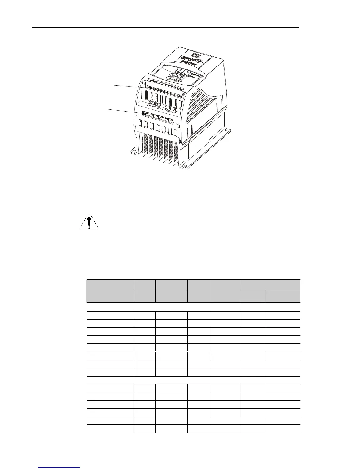
3.2.2 Location of the Power,
Grounding and Control
Connections
Control XC1
Power
Figure 3.5 - Location of the Power and Control Connections
Circuit-Breaker
Rated Inverter
Current [A]
Motor
Wiring
[mm²]
Grounding
Wiring
[mm²]
Power
Cables
[mm²]
Maximum
Cables
[mm²]
Current
WEG
Model
SINGLE-PHASE MODELS
1.6 (200-240 V ) 1.5 2.5 1.5 2.5 6 MPW 25-6.3
1.6 (110-127 V ) 1.5 2.5 1.5 2.5 10 MPW25-10
2.6 (200-240 V ) 1.5 2.5 1.5 2.5 10 MPW25-10
2.6 (110-127 V ) 1.5 2.5 2.5 2.5 16 MPW25-16
4.0 (200-240 V ) 1.5 2.5 1.5 2.5 16 MPW25-16
4.0 (110-127 V ) 1.5 4.0 2.5 4.0 20 MPW25-20
7.3 (200-240 V ) 2.5 4.0 2.5 4.0 20 MPW25-20
10.0 (200-240 V) 2.5 4.0 4.0 4.0 25 MPW25-25
THREE-PHASE MODELS
1.6 (200-240 V ) 1.5 2.5 1.5 2.5 2.5 MPW 25-2.5
2.6 (200-240 V ) 1.5 2.5 1.5 2.5 6.3 MPW 25-6.3
4.0 (200-240 V ) 1.5 2.5 1.5 2.5 10 MPW25-10
7.3 (200-240 V ) 2.5 4.0 2.5 4.0 15 MPW25-15
10.0 (200-240 V) 2.5 4.0 4.0 4.0 20 MPW25-20
15.2 (200-240 V) 4.0 4.0 4.0 4.0 25 MPW25-25