15
CHAPTER 2 - GENERAL INFORMATION
2.3 ABOUT THE
CFW-10
The CFW-10 frequency inverter is fitted with the V/F (scalar) control
method.
The V/F (scalar) mode is recommended for more simple applications
such as pump and fan drives. In these cases one can reduce the motor
and inverter losses by using the "Quadratic V/F" option, that results in
energy saving.
The V/F mode is also used when more than one motor should be
driven simultaneously by one inverter (multimotor application).
Chapter 9 shows the different power lines and additional technical
information
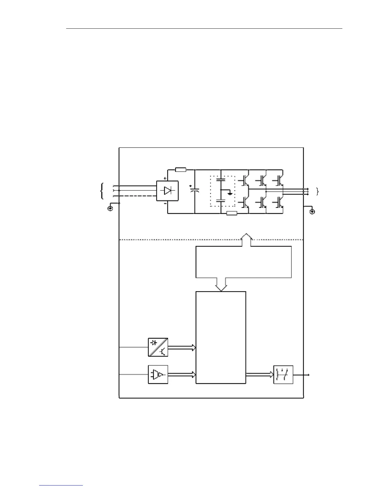
The block diagram below gives a general overview of the CFW-10.
Figure 2.1 - CFW-10 Block Diagram for models 1.6 A, 2.6 A and 4.0 A / 200-240 V (single-phase)
and 1.6 A, 2.6 A, 4.0 A and 7.3 A/200-240 V (three-phase)
Power
Supply
L/L1
PE
Analog
Input
(AI1)
Digital
Inputs
(DI1 to DI4)
POWER
CONTROL
POWER SUPPLY AND
CONTROL/POWER INTERFACES
"CCP10"
CONTROL BOARD
WITH DSP
Relay
Output
(RL1)
Motor
U
V
W
Rsh
NTC
RFI Filter
N/L2
L3