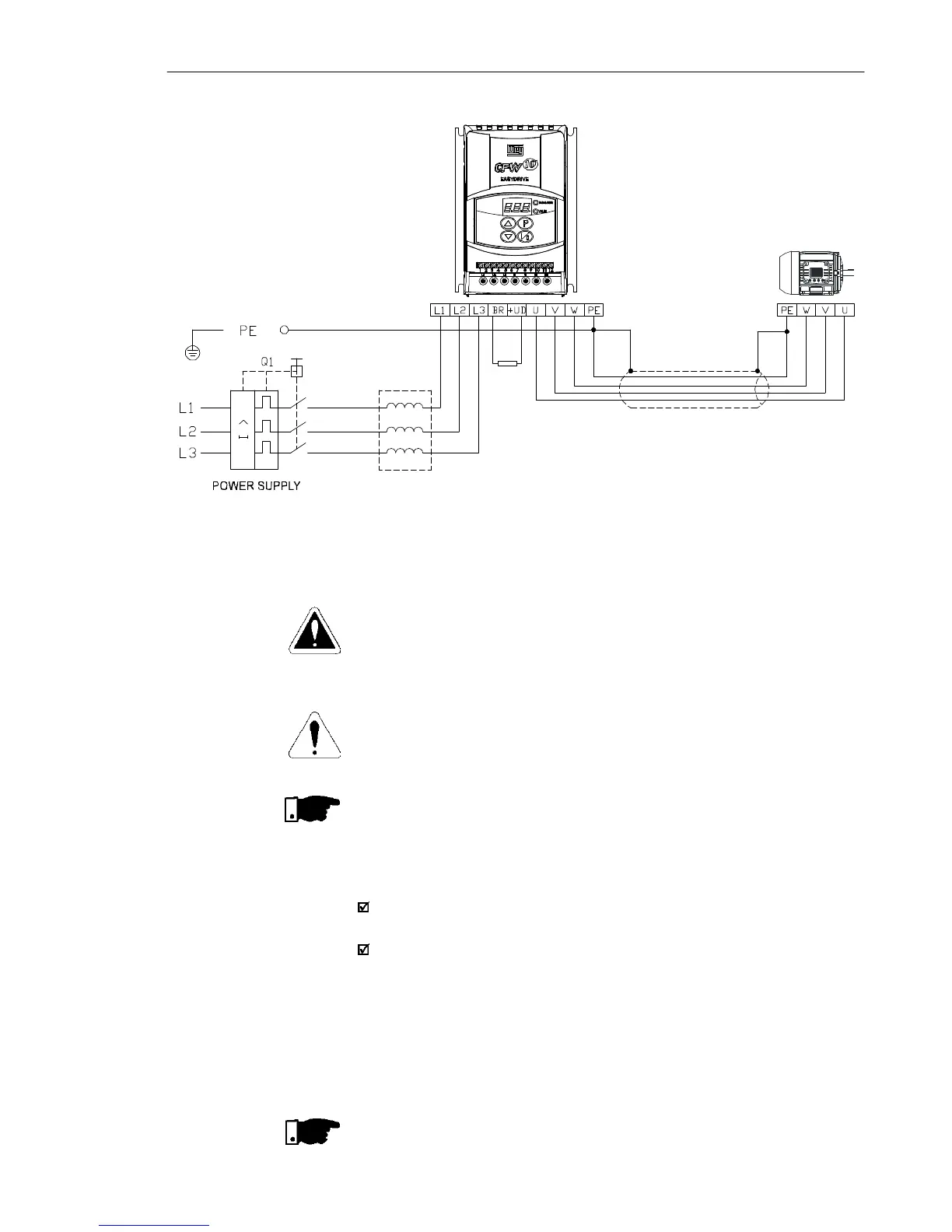
Figure3.6 d) - Grounding and power supply connections
d) Models 10.0A and 15.2 A/200-240 V (three-phase)
DANGER!
Use a disconnecting device at the drive AC-input power supply. This
device shall be capable of disconnecting the drive from the power
supply when necessary (for maintenance purposes, for instance).
ATTENTION!
The drive AC-input power supply shall have a grounded neutral
conductor.
NOTE!
The AC-input voltage shall match the drive rated voltage.
Supply line capacity:
The CFW-10 is capable of withstanding up to 30.000 symmetrical
rms Amperes at 127 V/240 V.
If the CFW-10 is installed in networks with higher symmetrical rms
currents (> 30.000 Amps), an appropriate protection mean shall
be provided (fuses or circuit breaker).
Line Reactors
The use of line reactors is dependent upon several factors. Refer to
Chapter 8.2 in order to understand these requirements.
NOTE!
Capacitors for power factor correction are not required at the input
(L/L1, N/L2, L3) and shall not be connected at the output (U, V, W).
3.2.4.1 AC Input
Connection