104
CHAPTER 8 - OPTIONS AND ACCESSORIES
The use of a three-phase load reactor, with an approximate 2 % voltage
drop, adds an inductance at the inverter output to the motor. This
decreases the dV/dt (voltage rising rate) of the pulses generated at
the inverter output. This practice reduces the voltage spikes on the
motor windings and the leakage currents that may be generated when
long cables between inverter and motor (as a function of the
"transmission line" effect) are used.
WEG Motor with voltages up to 460 V, no use of load reactor is
required, since the insulation of the motor wires support the operation
bi the CFW-10. If the cables between inverter and motor are longer
than 100 m (330 ft), the cable capacitance to ground increases. In
this case it is also recommended to use a load reactor.
8.3 LOAD
REACTOR
As an alternative criterion, we recommend to add a line reactor
always the transformer that supplies the inverter has rated output
higher than indicated in table below:
Inverter Model
1.6 A and 2.6 A/200-240 V
4 A/200-240 V
1.6 A, 2.6 A and 4.0 A/
110-127 V
7.3 A/220-240 V
10.0 A/200-240 V
15.2 A/200-240 V
Power of the Transformer [kVA]
30 x rated apparent power of the inverter [kVA]
6 x rated apparent power of the inverter [kVA]
6 x rated apparent power of the inverter [kVA]
10 x rated apparent power of the inverter [kVA]
7.5 x rated apparent power of the inverter [kVA]
4 x rated apparent power of the inverter [kVa]
Note: The value for the rated apparent power can be obtained in section 9.1 of
this manual.
Table 8.2 - Alternative criteria for use of line reactor - Maximum values of the
transformerpower
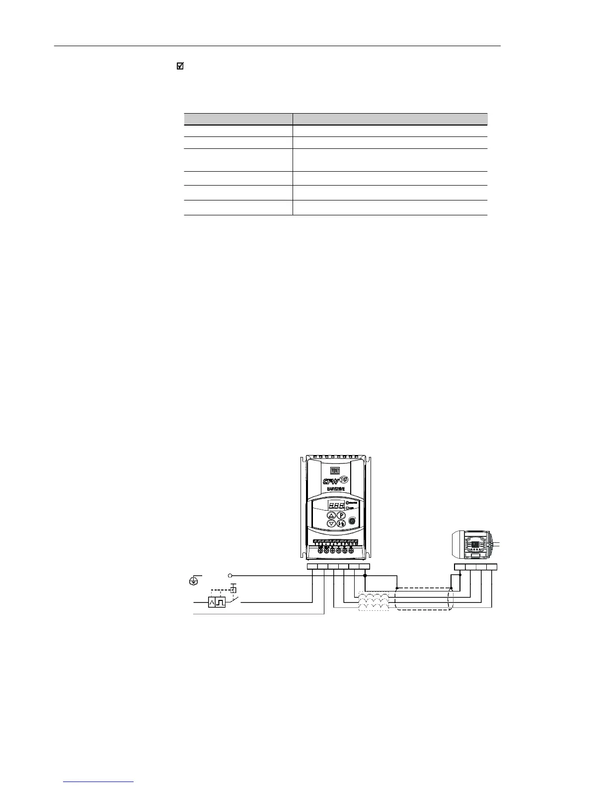
PE
U
V
W
SHIELD
N/L2
U V W PE
L/L1
LOAD
REACTOR
LINE
L/L1
PE
Q1
N/L2
Figure 8.3 - Load Reactor Connection
The rheostatic braking is used when short deceleration times are
required or when high inertia loads are driven.
For the correct braking resistor sizing the following application data
shall be considered: deceleration time, load inertia, braking duty cycle,
etc.
8.4 RHEOSTATIC
BRAKING