47
CHAPTER 4
KEYPAD (HMI) OPERATION
This chapter describes the CFW-10 operation via Human-Machine
Interface (HMI), providing the following information:
General keypad description (HMI);
Use of the keypad (HMI);
Inverter parameters arrangement;
Alteration mode parameters (programming);
Description of the status indicators.
4.1 KEYPAD (HMI)
DESCRIPTION
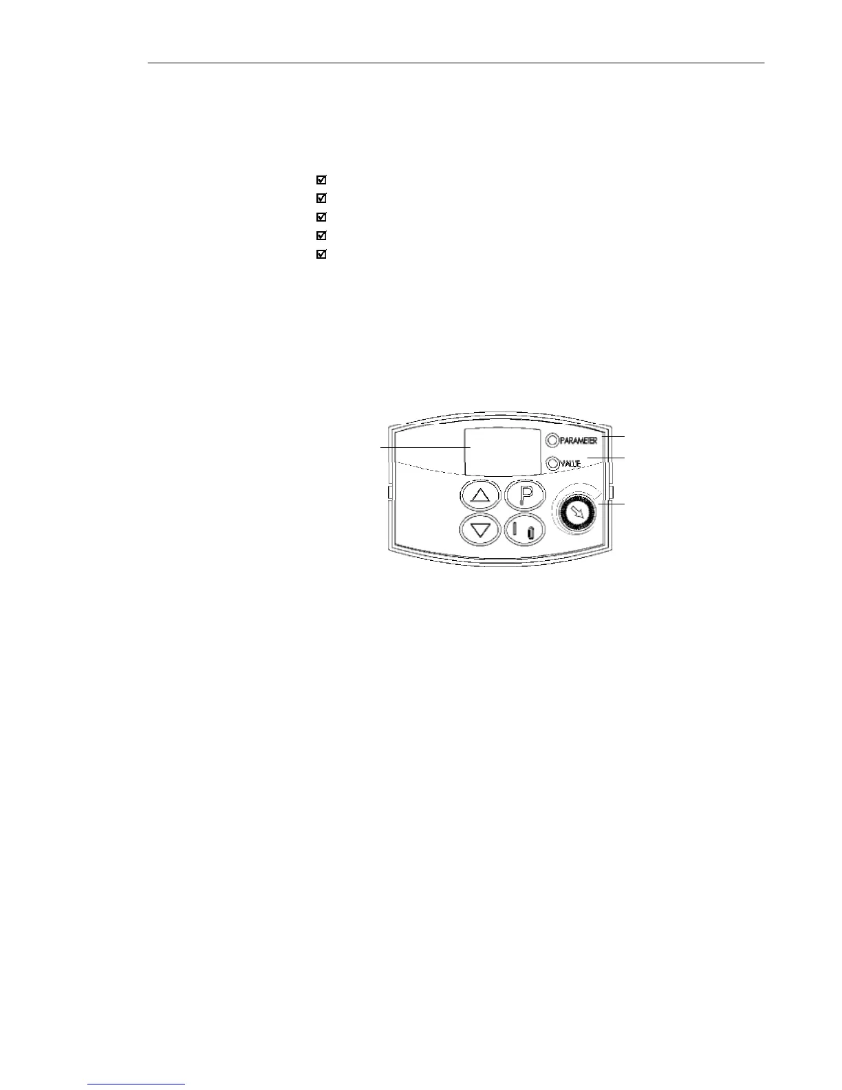
The standard CFW-10 keypad has a LED display with 3 digits of 7
segments, 2 status LEDs and 4 keys. Figure 4.1 shows the front
view of the keypad and indicates the position of the Display and the
status LEDs. CFW-10 Plus version still has a potentiometer for speed
setting.
Functions of the LED Display:
The Led Display shows the fault and status messages (see Quick
Parameter Reference, Fault and Status), the parameter number and
its value.
Functions of the LED´s “Parameter” and “Value”:
Inverter indicates the parameter number:
Green Led OFF and red Led ON.
Inverter indicates the parameter content:
Green Led ON and red Led OFF.
Potentiometer Function
Increase/Decrease the speed (only available on Plus version)
LED Display
LED "Parameter"
LED "Value"
Potentiometer (Only
available on Plus version)
Figure 4.1 - CFW-10 keypad (HMI)