109
CHAPTER 9 - TECHNICAL SPECIFICATIONS
The values shown in the table were calculated by considering the rated
inverter current, input voltage of 220 V.
(2) Rated current is valid for the following conditions:
Relative air humidity: 5 % to 90 %, non condensing.
Altitude: 1000 m up to 4000 m (3.300 ft up to 13.200 ft) – current
derating of 1 % for each 100 m (330 ft) above 1000 m (3.300 ft)
altitude.
Ambient temperature: 0 ºC to 50 ºC (32 ºF to 122 ºF). For the
15.2 A model and models with Built-in filter the temperature is
0 to 40 °C (32 ºF to 104 ºF).
The rated current values are valid for the switching frequencies of
2.5 kHz to 10 kHz (factory setting = 5 kHz, 2.5 kHz for the 15.2 A
model).
For higher switching frequencies, 10.1 kHz to 15 kHz, consider
the values shown in the description of the parameter P297 (refer
to chapter 6).
(3) Maximum Current:
Inverter supports an overload of 50 % (maximum output current
= 1.5 x the rated output current) during 1 minute for each 10
minutes of operation.
For higher switching frequencies, 10.1 kHz up to 15 kHz, consider
1.5 times the value showed in parameter description P297 (see
chapter 6).
(4) The indicated motor power ratings are only orientative values for IV-
pole motors and normal duty loads. The precise inverter sizing
must consider the actual motor nameplate and application data.
NOTE!
(1) The power rating in kVA is determined by the following equation:
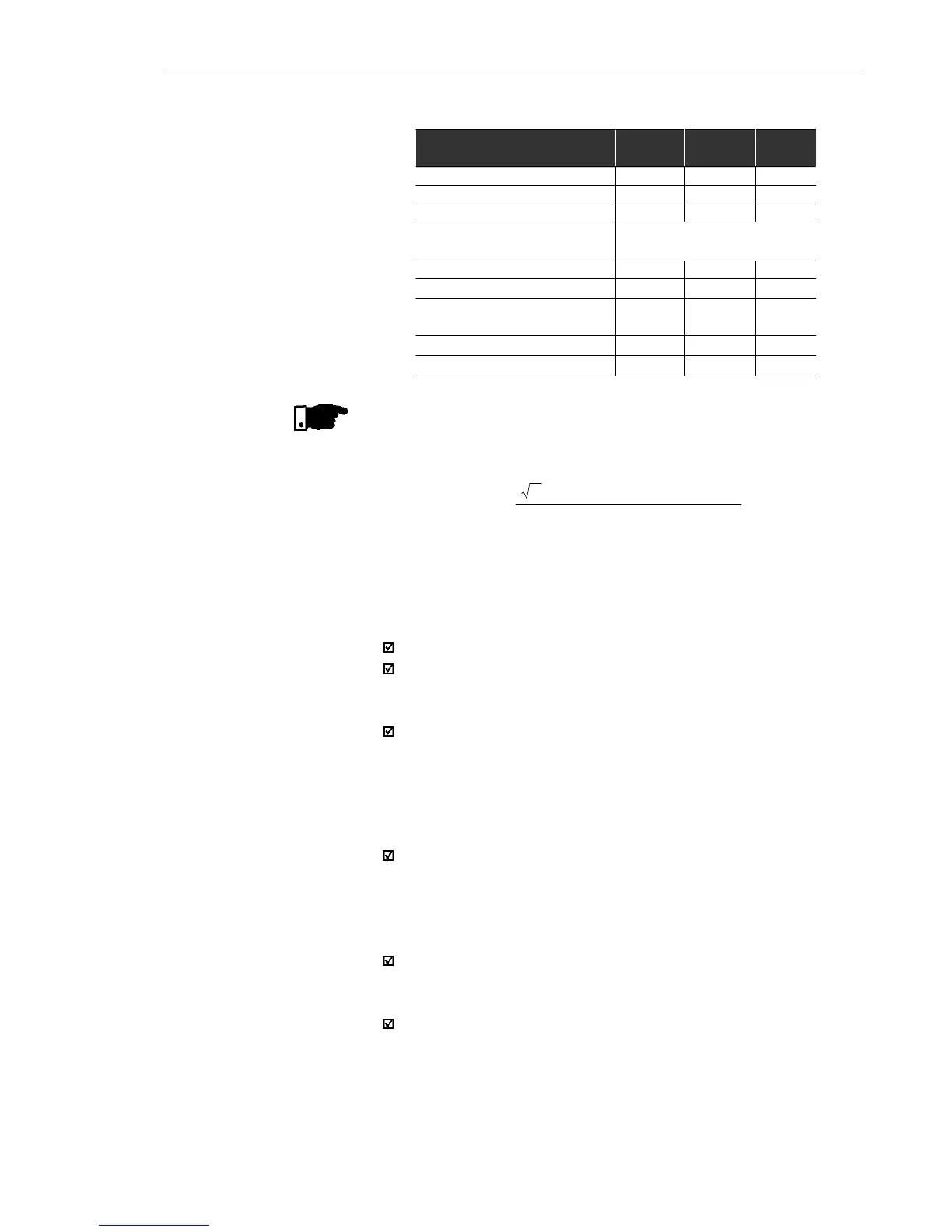
9.1.3 Power Supply: 110/127 V – Single-phase
Model: Current/Voltage (V)
Power (kVA)
(1)
Rated Output Current (A)
(2)
Max. Output Current (A)
(3)
Power Supply
Rated Input Current (A)
Switching Frequency (kHz)
Max. Motor Power (cv)
(4) (5)
Watt Losses (W)
RheostaticBraking
1.6/
110-127
0.6
1.6
2.4
7.1
10
0.25 HP/
0.18 kW
40
No
2.6/
110-127
1.0
2.6
3.9
11,5
10
0.5 HP/
0.37 kW
45
No
Single-Phase
4.0/
100-127
1.5
4.0
6.0
17.7
10
1 HP/
0.75 kW
60
Yes
P (kVA) =
3 . Voltage (V) . Current (A)
1000