26
CHAPTER 3 - INSTALLATION AND CONNECTION
3.1.3.1 Panel
Mounting
When drives are installed inside panels or inside closed metallic
boxes, proper cooling is required to ensure that the temperature
around the drive will not exceed the maximum allowable temperature.
Refer to Section 9.1 for Power Dissipation data.
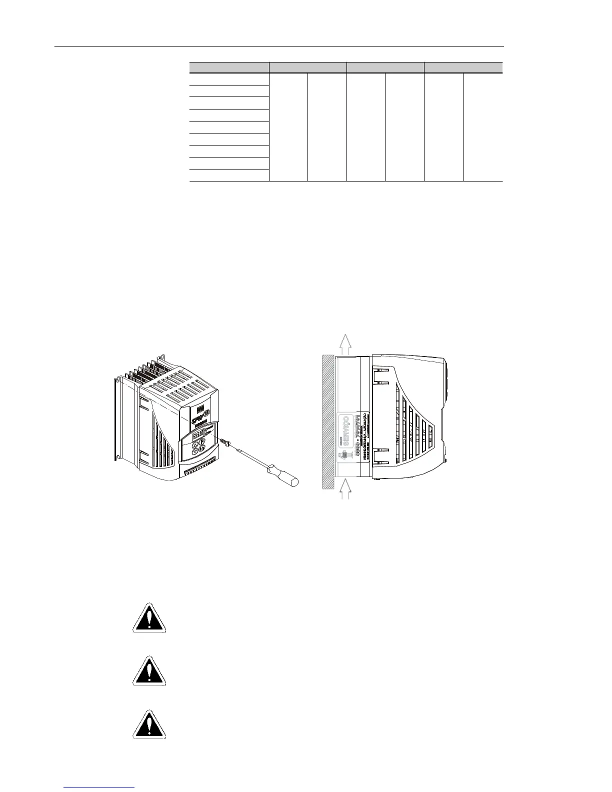
3.1.3.2 Mounting
Surface
Figure 3.3 shows the installation procedure of the CFW-10 on a
mounting surface.
Figure 3.3 - Mounting Procedures for the CFW-10
3.2 ELECTRICAL INSTALLATION
DANGER!
The information below will be a guide to achieve a proper installation.
Follow also all applicable local standards for electrical installations.
DANGER!
Be sure the AC input power has been disconnected before making
any terminal connection.
DANGER!
The CFW-10 shall not be used as an emergency stop device. Use
additional devices proper for this purpose.
Air Flow
Table 3.2 - Free space requirements
CFW-10 Model
1.6 A / 200-240 V
2.6 A / 200-240 V
4.0 A / 200-240 V
7.3 A / 200-240 V
10.0 A/200-240 V
15.2 A/200-240 V
1.6 A / 110-127 V
2.6 A / 110-127 V
4.0 A / 110-127 V
A B C
30 mm 1.18 in 50 mm 2 in 50 mm 2 in