110
CHAPTER 9 - TECHNICAL SPECIFICATIONS
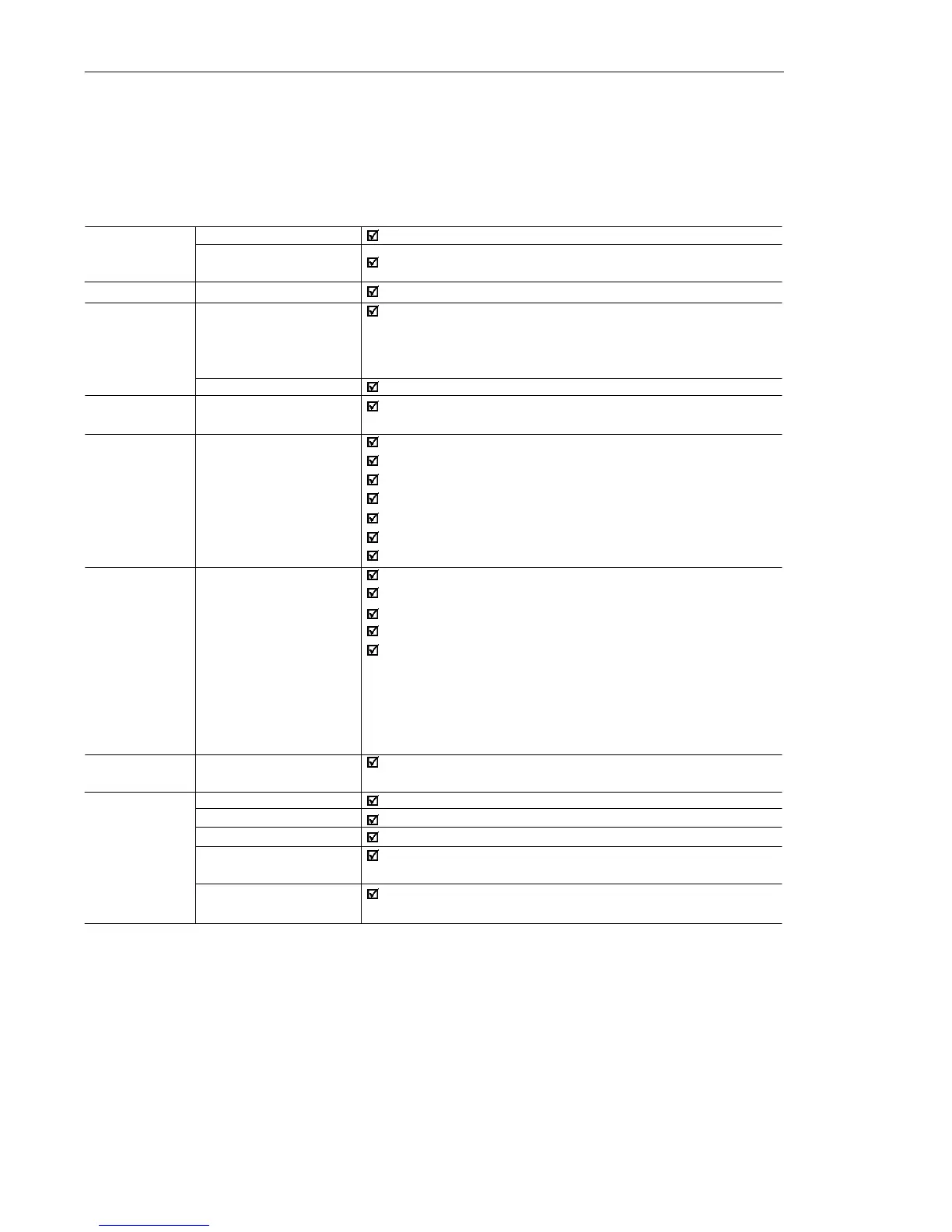
9.2 ELECTRONIC/GENERAL DATA
Applied Voltage V/F (scalar)
0 to 300 Hz, resolution: 0.01 Hz.
Speed regulation: 1 % of the rated speed.
1 isolated input, resolution: 7 bits, (0 to 10) V or (0 to 20) mA, or
(4 to 20) mA,
Impedance: 100 k [(0 to 10) V], 500 [(0 to 20) mA or
(4 to 20) mA], programable function.
4 isolated digital inputs, 12 Vdc, programmable functions.
1 relay with reverse contacts, (250 Vac - 0.5 A / 125 Vac 1.0 A /
30 Vdc 2.0A), programmable functions.
Overcurrent/output short-circuit
Undervoltage and overvoltage at the power part
Inverter overtemperature
Motor/inverter overload (I x t)
External fault
Programming error
Defective inverter
4 keys: start/stop, increment, decrement and programming,
LEDs display: 3 digits with 7 segments
LEDs for Parameter and its Contecnt Indication
It permits access/alteration of all parameters
Display accuracy:
- current: 10 % of the rated current
- voltage resolution: 1 V
- frequency resolution: 0.1 Hz
- 1 potentiometer for the output frequency variation (available
only in the Plus version)
For all models
Inverters and semicondutors
Power Conversion Equipment
Electronic equipment for use in power installations
Safety requirements for electrical equipment for measurement,
control and laboratory use
EMC product standard for adjustable speed electrical power
drive systems, (with external filter)
CONTROL METHOD
OUTPUT
FREQUENCY
PERFORMANCE V/F CONTROL
INPUTS ANALOG
(CCP10 Board)
DIGITAL
OUTPUT RELAY
(CCP10 Board)
SAFETY PROTECTION
KEYPAD STANDARD HMI
(HMI)
DEGREE OF IP20
PROTECTION
STANDARDS IEC 146
UL 508 C
EN 50178
EN 61010
EN 61800-3
(5) WEG inverters are supplied with parameter settings for WEG IV
pole standard motors, 60 Hz, 220 V and outputs as indicated
above.