39
CHAPTER 3 - INSTALLATION AND CONNECTION
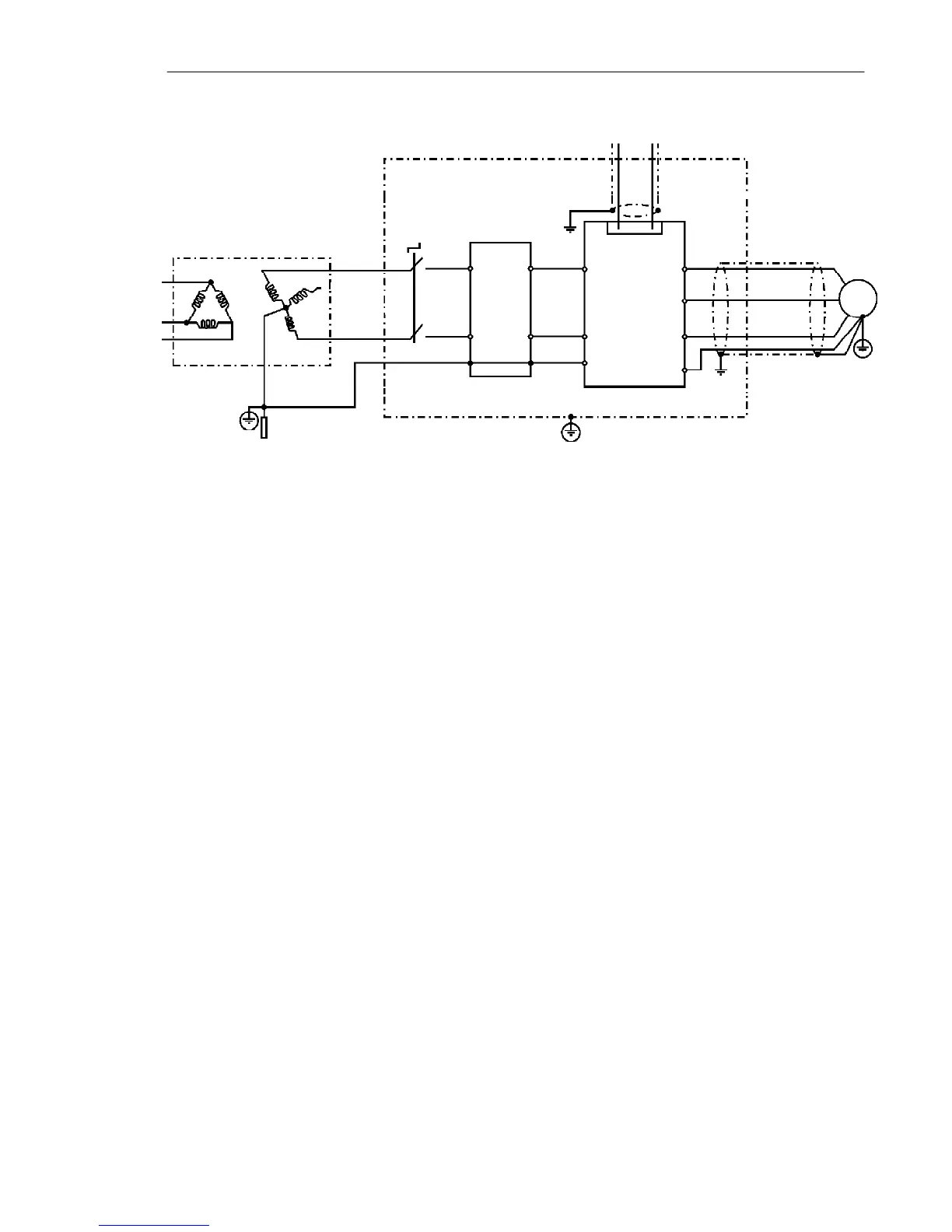
Figure 3.13 below shows the EMC filters connection.3.3.1 Installation
Figure 3.13 - EMC filter connection - general condition
The following items are required in order to have an appropriated
installation:
1) The motor cable shall be armored, or installed inside a metallic
conduit or trunking with equivalent attenuation. Ground the screen/
metallic conduit at both ends (inverter and motor).
2) Control (I/O) and signal wiring shall be shielded or installed inside
a metallic conduit or trunking with equivalent attenuation.as possible.
3) The inverter and the external filter shall be closely mounted on a
common metallic back plate. Ensure a good electrical connection
between the inverter heatsink, the filter frame and the back plate.
4) The wiring between the filter and the inverter shall be kept as short.
5) The cable shield (motor and control) shall be solidly connected to
the common back plate, using metallic brackets.
6) Grounding shall be performed as recommended in this user’s guide.
7) Use short and thick cables to ground the external filter or inverter.
When an external filter is used, ground only the filter (input) - the
inverter ground connection is performed through the metallic back
plate.
8) Ground the back plate using a braid, as short as possible. Flat
conductors (e.g. braids or brackets) have lower impedance at high
frequencies.
9) Use cable glands whenever possible.
Transformer
Grounding rod
Protective Grounding
Motor
PE
CFW-10
L2/N
L1/L
PE
PE
XC1
1 to 12
U
Controling and signal wiring
V
W
PE
L1/L
L2/N
L2
L1
PE
External
input RFI
filter
Metalic cabinet when necessary