106
CHAPTER 8 - OPTIONS AND ACCESSORIES
Connect the braking resistor between the +UD and BR power
terminals (Refer to Section 3.2.1 and fig. 3.6);
Make this connection with a twisted pair. Run this cable separately
from any signal or control wire. Size the cable cross section
according to the application, considering the maximum and RMS
current;
If the braking resistor is installed inside the inverter panel, the
additional heat dissipated by the resistor shall be considered when
defining the panel ventilation.
DANGER!
The internal braking circuitry of the inverter as well as the braking
resistor may be damaged if they are not properly sized and/or if the
input power supply exceeds the maximum admissible value. In this
case, the only guaranteed method to avoid burning the resistor and
to eliminate the risk of fire is the installation of a thermal overload
relay in series with the resistor and/or the installation of a thermostat
on the resistor body, wiring it in a way to disconnect the inverter power
supply in case of overload, as shown below:
8.4.2 Installation
NOTE!
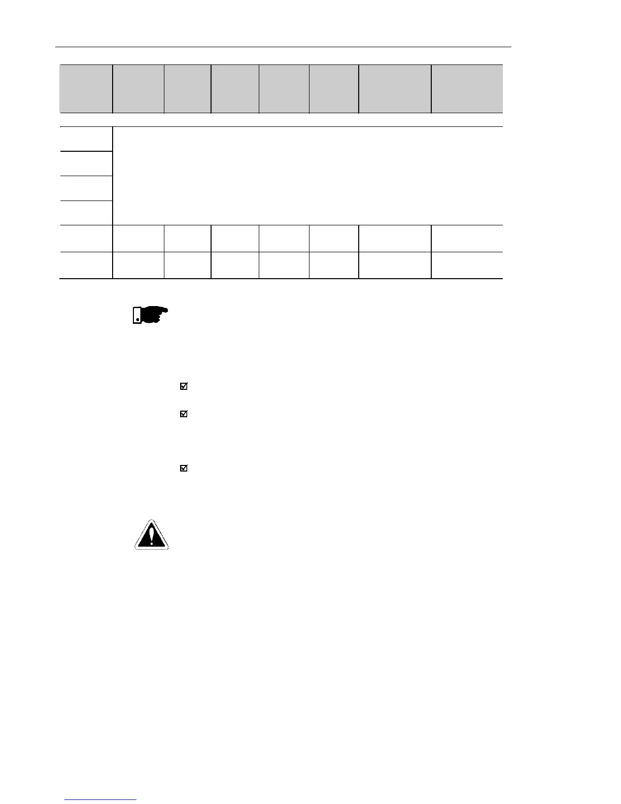
Data presented in table 8.3 were calculated for the maximum power
admissible for the frequency converter. For smaller braking power,
another resistor can be used according to the application.
CFW -10
Model
V
max
(Maximum
Resistor
Voltage)
Maximum
Braking
Current
P
max
(Resistor
Peak
Power)
Maximum
RMS
Braking
Current
P
rms
(Resistor
Maximum
Power)
Recommended
Resistor
Recommended
Wiring
THREE-PHASE
1.6 A /
200-240 V
2.6 A /
200-240 V
4.0 A /
200-240 V
7.3 A /
200-240 V
Braking not available
10.0 A /
200-240 V
410 V 11 A 4.3 kW 10 A 4.3 kW 39 (ohms)
2.5 mm² /
14 AWG
15.2 A /
200-240 V
410 V 11 A 4.3 kW 10 A 4.3 kW 39 (ohms)
2.5 mm² /
14 AWG
Table 8.3 (cont.) - Recommended braking resistors