22
CHAPTER 3
INSTALLATIONAND CONNECTION
3.1 MECHANICAL
INSTALLATION
3.1.1 Environment
This chapter describes the procedures for the electrical and
mechanical installation of the CFW-10.
These guidelines and suggestions must be followed for proper
operation of the CFW-10.
The location of the inverter installation is an important factor to assure
good performance and high product reliability. For proper installation,
we make the following recommendations:
Avoid direct exposure to sunlight, rain, high moisture and sea air.
Avoid exposure to gases or explosive or corrosive liquids;
Avoid exposure to excessive vibration, dust, oil or any conductive
particles or materials.
Environmental Conditions:
Temperature : 0 ºC to 50 ºC (32 ºF to 122 ºF) - nominal conditions,
except for the 15.2 A model with Built-in filter (0 to 40 °C).
Relative Air Humidity: 5 % to 90 % - non-condensing.
Maximum Altitude: 1000 m (3.300 ft) - nominal conditions.
From 1000 m to 4000 m (3.300 ft to 13.200 ft): with 1 % current
derating for each 100 m (330 ft) above 1000 m (3.300 ft).
Pollution Degree: 2 (according to EN50178 and UL508C).
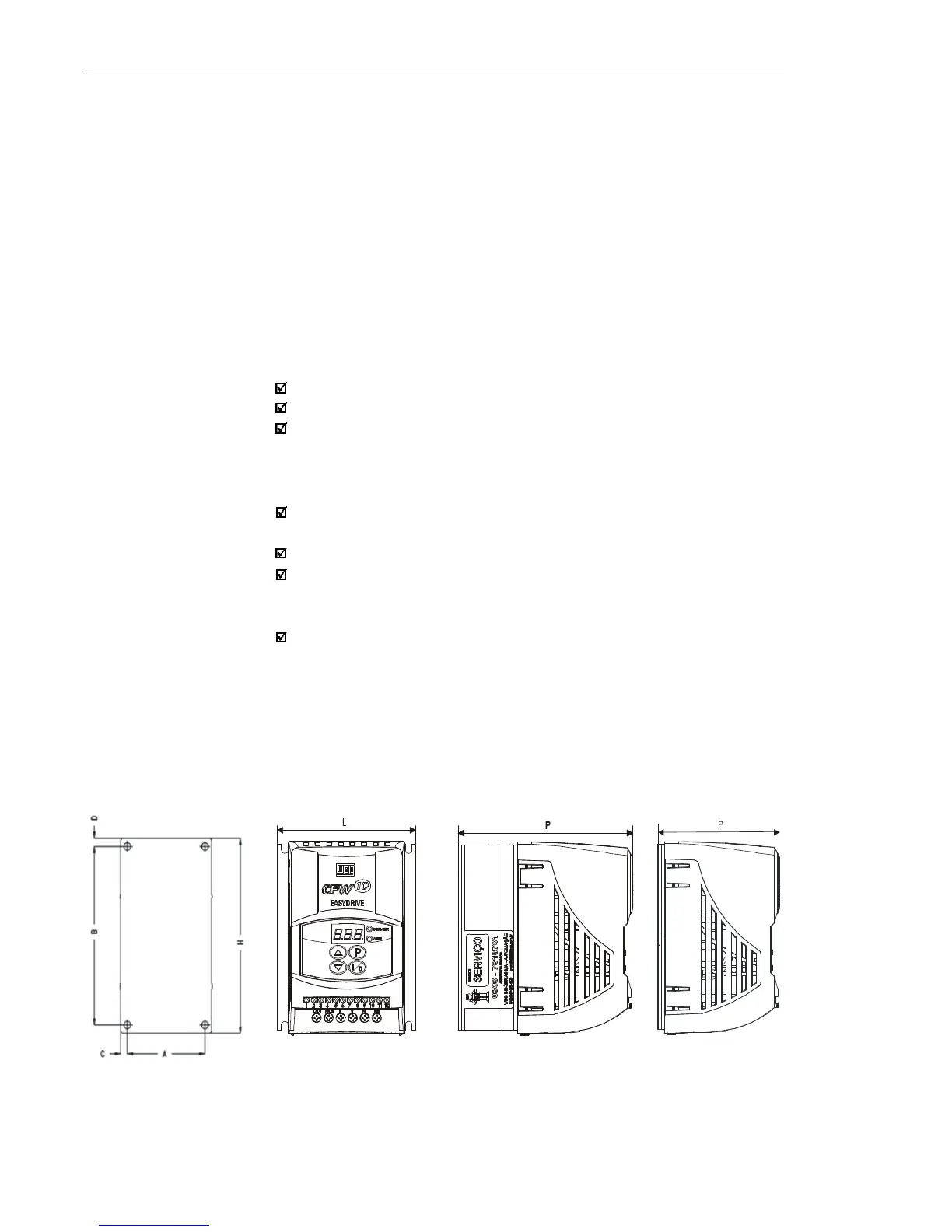
External dimensions and mounting holes for the CFW-10 shall be
according to figure 3.1 and table 3.1.
3.1.2 Dimensional of
CFW-10
MOUTING BASE
VIEW
FRONTAL
VIEW
SIDE VIEW
(STANDARD VERSION)
Figure 3.1 - Dimensional of CFW-10 - Sizes 1, 2 and 3
SIDE VIEW
(COLD PLATE
VERSION)