37
CHAPTER 3 - INSTALLATION AND CONNECTION
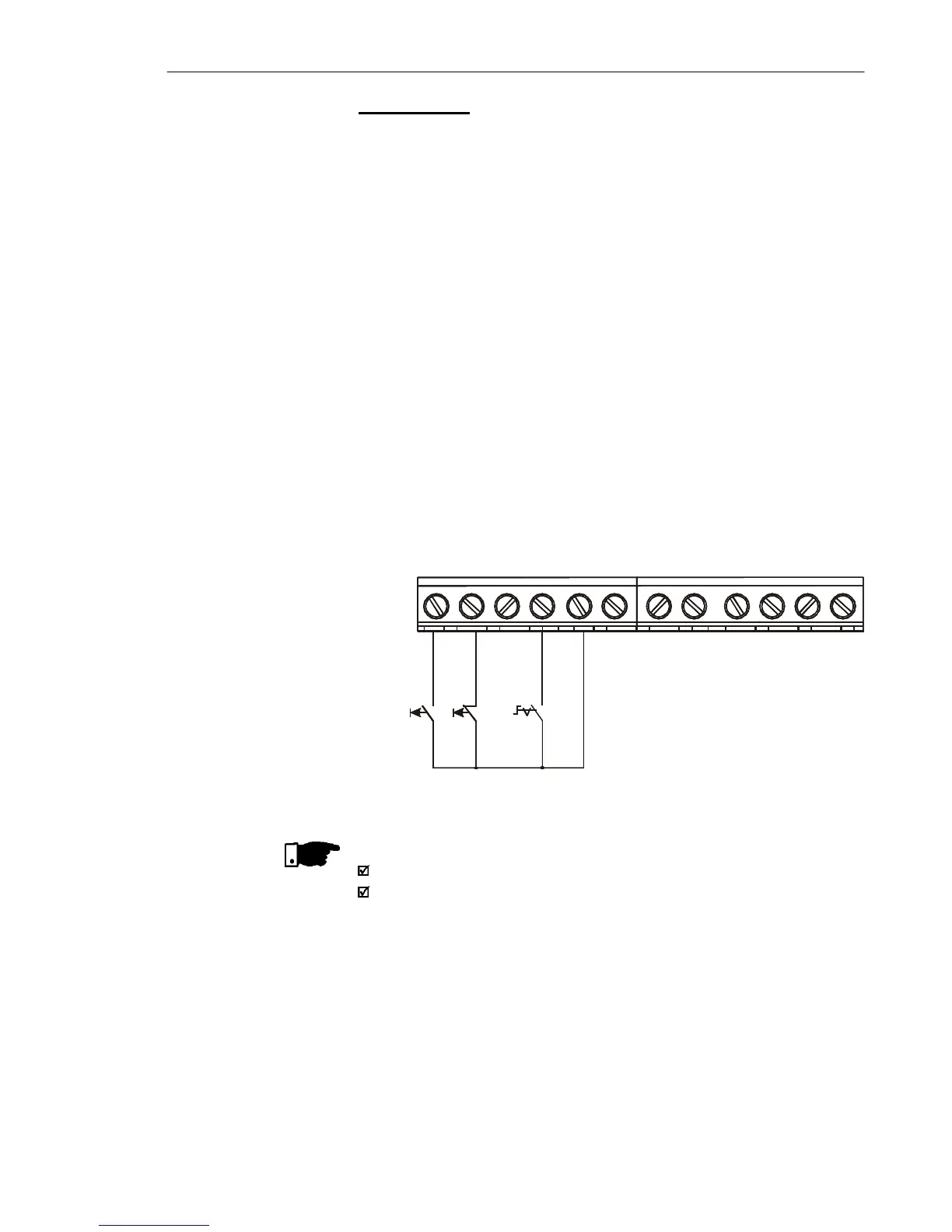
Figure 3.11 - Wiring for Connection 3
NOTE!
S1 and S2 are push buttons, NO and NC contact, respectively.
The speed reference can be realized via Analog Input AI1 (as in
connection 2), via keypad (HMI-CFW10), or via any other source
(See description of parameters P221 and P222).
When a line fault occurs by using this connection with the motor
running and the S1 and S2 switches are in original position (S1
openned and S2 closed), the inverter will not be enabled
automatically as soon as the line is re-restablished.
The drive will be enabled only when S1 switch is closed. (Pulse on
the “Start” digital input).
The Start/Stop function is described in Chapter 6.
S1: Start
S2: Stop
S3: FWD/REV
DI1 - Start (Start)
DI2 - Stop (Stop)
DI3 - Local/Remote
GND
AI1 (0.4 to 20 mA)
GND
AI1 (0 to 10 Vdc)
+10 Vdc
NC
Common
NO
DI4 - Forward/Reverse
S3S2
1 2 3 4 5 6 7 8 9 10 11 12
S1
Connection 3
Start/Stop function enabling (three-wire control):
Set DI1 to Start: P263 = 13
Set DI2 to Stop: P264 = 14
Set P229 = 1 (commands via terminals) if you want the 3-wire control
in local mode.
Set P230 = 1 (commands via terminals) if you want the 3-wire control
in remote mode.
FWD / REV Selection:
Program P265 = 5 (DI3) or P266 = 5 (DI4), according to the selected
digital input (DI).
If P265 and P266 0, the direction of rotation is always FWD.