35
CHAPTER 3 - INSTALLATION AND CONNECTION
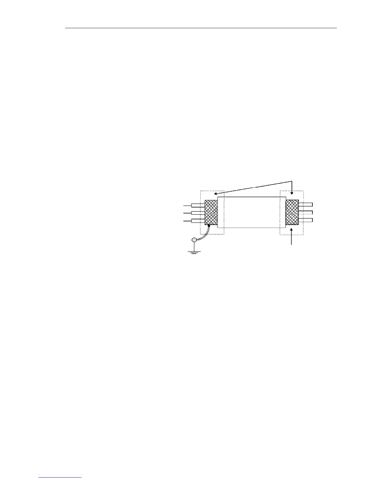
Figure 3.9 - Shield connection
Connect to earth
Do not
ground
Inverter
side
Insulate with
tape
4) For wiring distances longer than 50 m (150 ft), the use of
galvanic isolators is required for the XC1:6 to XC1:9 analog signals.
5) Relays, contactors, solenoids or eletromagnetic braking coils
installed near inverters can eventually generate interferences
in the control circuit. To eliminate this interference, connect RC
suppressor in parallel with the coils of AC relays. Connect
free-wheeling diode in case of DC relays.
6) When analog reference (AI1) is used and the frequency
oscillates (problem caused by electromagnetic interference)
connect XC1:7 to the inverter grounding bar.
During the signal and control wire installation note the following:
1) Cable cross section: (0.5 to 1.5) mm² / (20 to 14) AWG.
2) Max. Torque: 0.50 N.m (4.50 lbf.in).
3) XC1 wiring must be connected with shielded cables and
installed at least 10 cm (3.9 in) minimum separately from other
wiring (power, control at 110/220 V, etc) for lengths up to
100 m (330 ft) and 25 cm (9.8 in) minimum for total lengths over
100 m (330 ft).
If the crossing of these cables is unavoidable, install them
perpendicular, maintaining a mimimum separation distance
of 5 cm (2 in) at the crossing point.
Connect the shield as shown below: