63
CHAPTER 6 - DETAILED PARAMETER DESCRIPTION
Range
[Factory Setting]
Parameter Description / Notes
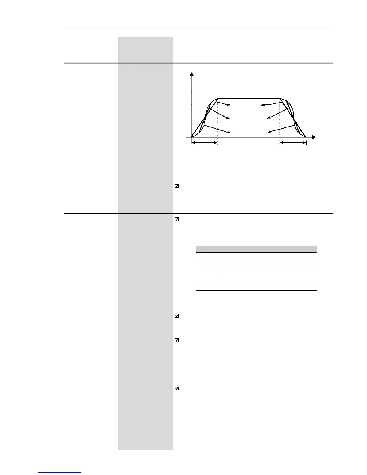
Output Frequency
(Motor Speed)
Linear
t (s)
t
accel. time
(P100/102)
t
decel. time
(P101/103)
50 % S ramp
100 % S ramp
Figure 6.4 - S or linear Ramp
It is recommended to use the S ramp with digital
frequency/speed references.
P120 0 to 3
Digital Reference [ 1 - active]
Backup -
Defines if the inverter should save or not the last used
digital reference. This backup function is only
applicable to the keypad reference (P121).
P120
0
1
2
3
Reference Backup
Inactive
Active
Active, but always given by P121,
independently of the source reference
Active after ramp
Table 6.2 - Backup configuration of digital reference
If the digital reference backup is inactive (P120 = 0),
the reference will be equal to the minimum frequency
every time the inverter is enabled, according to P133.
When P120 = 1, inverter saves automatically the di-
gital reference value, (independent of the reference
source, keypad, EP). This occurs always when inver-
ter disable is present, independent of the present
disable condition (ramp or general), error or
undervoltage.
When P120 = 2, the initial reference will be given by
P121,and saved always the inverter is enabled.
Application example: reference via EP when inverter
is disabled via digital input and decelerates EP
(coming to reference 0). However at a new enable, it
is desired that the inverter returns to a frequency
different from the minimum frequency, which will be
saved at Parameter P121.