66
CHAPTER 6 - DETAILED PARAMETER DESCRIPTION
Range
[Factory Setting]
Parameter Description / Notes
P133
(1)
0.0 to P134
Minimum [ 3.0 Hz ]
Frequency 0.1 Hz (< 100 Hz);
(F
min
) 1 Hz (> 99.9 Hz)
P134
(1)
P133 to 300
Maximum [ 66.0 Hz ]
Frequency 0.1 Hz (< 100 Hz);
(F
max
) 1 Hz (> 99.9 Hz)
Defines the maximum and minimum output frequency
(motor) when inverter is enabled.
It is valid for any type of speed reference.
The parameter P133 defines a dead zone when analog
inputs are used - see parameters P234 to P236.
P134 and the gain and offset of the analog input(s)
(P234, P236) define the scale and the range of the
speed variation via analog input. For more details see
parameters P234 to P236.
Compensates the voltage drop dueto the motor stator
resistance.It acts at low speeds by increasing the in-
verter output voltage, in order to maintain a constant
torque during the V/F operation.
The best setting is to program the lowest value for
P136 that still permits the motor start satisfactorily. If
thevalue is higher than required, an inverter overcurrent
(E00 or E05) may occur due to high motor currents at
low speeds.
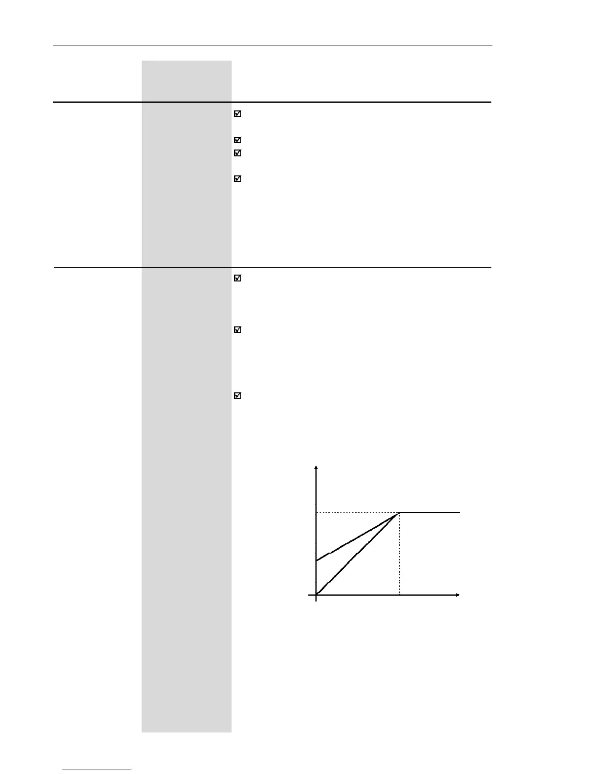
The setting P136 = 100 % corresponds tothemaximum
increment of the output voltage (30 % of P142).
Output Voltage
(% of the line voltage)
P142
0.3 x P136 x P142
0 P145
Output
frequency
a) P202 = 0
Figure 6.6 a) - V/F curve and details of the manual torque boost
(I x R compensation)
P136 0.0 to 100
Manual Torque [ 20.0 ]
Boost 0.1 %
(I x R
Compensation) For the 15.2 A
model the factory
adjustment is [6.0]