73
CHAPTER 6 - DETAILED PARAMETER DESCRIPTION
Range
[Factory Setting]
Parameter Description / Notes
Programs all parameters to the standard factory
default, when P204 = 5.
P204
(1)
0 to 999
Loads [ 0 ]
Factory -
Setting
In the event of a fault trip, except for E09, E24, E31
and E41, the inverter can start an automatic reset after
the time given by P206 is elapsed.
If P206 2 Auto-Reset does not occur.
If after Auto-Reset the same fault is repeated three
times consecutively, the Auto-Reset function will be
disabled. A fault is considered consecutive if it
happens again within 60 seconds after theAuto-Reset.
Thus if a fault occurrs four times consecutively, this fault
remains indicated permanently (and inverter disabled).
P206 0 to 255
Auto-Reset [ 0 ]
Time 1 s
P203
(1)
0 to 1
Special Functions [ 0 - None ]
Selection -
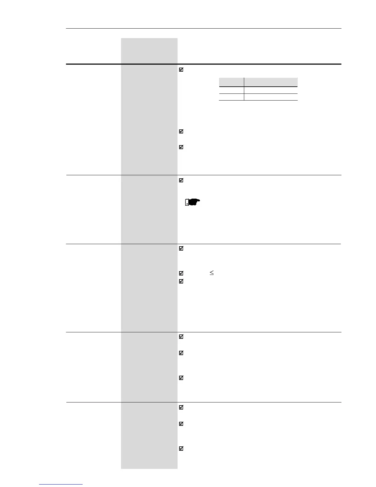
Selects or not the PID Regulator special function.
P203 Special Function
0 None
1 PID Regulator
Table 6.6 - P203 configuration to use or not the
PID regulator special function
For PID Regulator special function see detailed
description of the related parameters (P520 to P528).
When P203 is changed to 1, it is necessary to program
one of the digital inputs P263 to P266 for 27
(DIX = manual/automatic).
NOTE!
The parameters P142 (max. output voltage),
P145 (field weakening frequency), P156 (motor
overload current), P169 (maximum output current)
are not changed.
It allows that the read-only parameter P002 indicates
the motor speed in any value, for instance, rpm.
The indication of P002 is equal to the output frequency
value (P005) multiplied by the value of P208, i.e.,
P002 = P208 x P005.
Always when the value of the multiplication of P208 x
P005 is higher than 999, the displayed value remains
at 999.
P208 0.0 to 100
Reference Scale [ 1.0 ]
Factor 0.01 (< 10.0)
0.1 (> 9.99)
P219
(1)
0.0 to 15.0
Switching [ 15.0 ]
Frequency 0.1 Hz
Reduction
Point
Defines the point where there is automatic gradual
reduction of the switching frequency.
This improves considerably the measurement of the
output current at low frequencies, and consequently
improves the inverter performance.
In application where it is not possible to operate the
inverter at low frequencies, ex. 2.5 kHz (for instance,
due to acoustic noise), set P219 = 0.0.