85
CHAPTER 6 - DETAILED PARAMETER DESCRIPTION
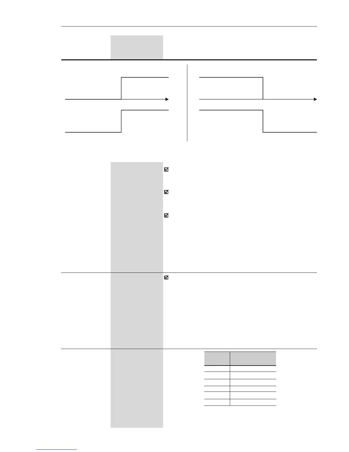
Figure 6.20 e) f) - Details about the operation of the relay output fucntions
e) Run
Stopped motor or
running by inertia
Time
OFFRelay
ON
Motor Running
f) No Fault
Time
OFF
Relay
Fault State (Exy)
Ready/Run State
ON
Range
[Factory Setting]
Parameter Unit Description / Notes
When the definition in the function name is true, the di-
gital output will be activated, i.e., the relay coil is
energized.
When the option 'Not used' has been programmed, the
relay output(s) will be disabled, i.e., the coil is not
energized.
Definitions of the used symbols in the functions:
Fs = P005 - output frequency (motor)
Fe = Reference frequency (ramp input frequency)
Fx = P288 - Fx frequency
Is = P003 - output current (motor)
Ix = P290 - Ix current
P288 0.0 to P134
Frequency Fx [ 3.0 Hz ]
0.1 Hz (< 100 Hz);
1 Hz (> 99.9 Hz)
P290 0 to 1.5 x P295
Current Ix [ 1.0 x P295 ]
0.1 A
Used in the relay output functions Fs > Fx, Fe > Fx e
Is > Ix (see P277).
P295 1.6 to 10.0
Inverter Rated [ According to
Current Inverter Rated
(I
nom
) Current ]
-
P295
1.6
2.6
4.0
7.3
10.0
15.2
Inverter Rated
Current (I
nom
)
1.6 A
2.6 A
4.0 A
7.3 A
10.0 A
15.2 A
Table 6.14 - Inverter rated current definition