87
CHAPTER 6 - DETAILED PARAMETER DESCRIPTION
Range
[Factory Setting]
Parameter Unit Description / Notes
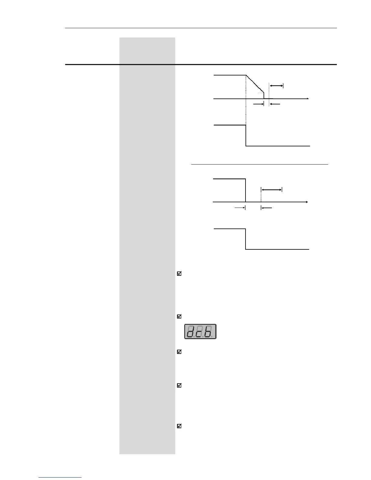
Before DC braking starts, there is a "Dead Time" (mo-
tor runs freely) required for the motor demagnetization.
This time is function of the motor speed at which the
DC braking occurs (output frequency).
During the DC braking the LED display flashes
.
If the inverter is enabled during the braking process,
this process will be aborted and motor operates
normally.
DC braking can continue its braking process even after
the motor has stopped. Pay special attention to the
dimensioning of the motor thermal protection for cyclic
braking of short times.
In applications where the motor current is lower than
the rated inverter current, and where thebraking torque
is not enough for the braking condition, please contact
WEG to optimize the settings.
Figure 6.21 - DC braking after ramp disable
Figure 6.22 - DC braking after general disable
P301
P300
DEAD
TIME
open
Time
DI - Start/Stop
0 V
Outpuit
frequency
(Motor
speed)
DC CURRENT
INJECTION
P300
open
Time
DEAD
TIME
IDC CURRENT
INJECTION
DI- General
Enable
Outpuit
frequency
(Motor
speed)
0 V