99
DETAILED PARAMETER DESCRIPTION
Range
[Factory Setting]
Parameter Unit Description / Notes
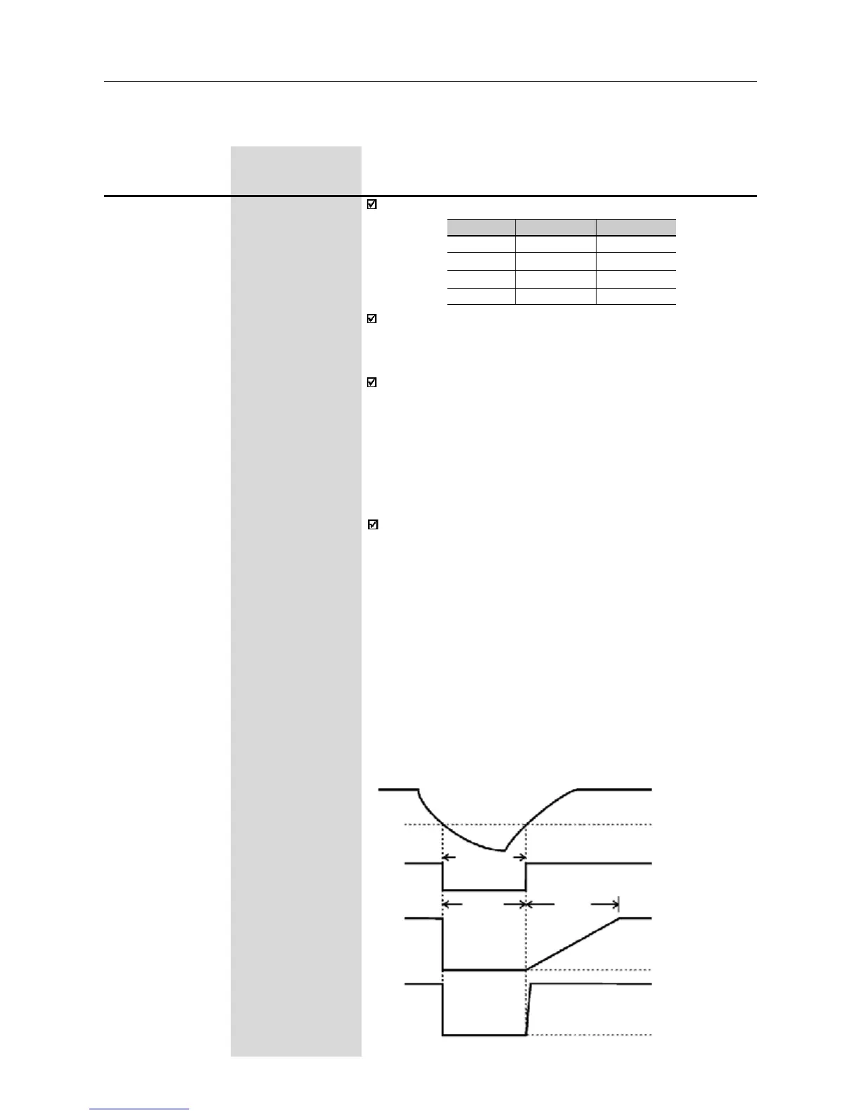
P311t<2s
t
disabled.
>t
dead time
Enabled
Disabled
DC link voltage
Undervoltage level
(E02)
PWM pulses
Output Voltage
0V
Output Frequency
(Motor Speed)
0Hz
P310
(1)
0...3
Flying Start and [ 0 - Inativas ]
Ride-Through -
P311 0.1...10.0s
Voltage Ramp [ 5.0s ]
0.1s
The parameter P310 selects the active function(s):
P310
0
1
2
3
Flying Start
Inactive
Active
Active
Inactive
Ride-Through
Inactive
Inactive
Active
Active
Parameter P311 sets the time required for the motor restart, both
for flying start function and the ride-through function. In other words, it
defines the time to set the output voltage starting from 0V and up to
reaching the rated voltage.
Operation of the flying start function:
- It allows the motor to start when it is running. This functions acts
only when the inverter is enabled. During the start, the inverter will
impose the speed reference, creating a voltage ramp with time
defined at P311.
- The motor can be started in conventional form, even when the
flying start has been selected (P310=1 or 2), adjusting one of the
digital inputs (D13 or D14) to 13 (flying start disable) and driving it
(0V) during the motor start.
Ride-Through operation:
- Permits the inverter recovery, without disabling by E02
(undervoltage), when a momentary voltage drop in the line occurs.
The inverter will be disabled only by E02, if the voltage drop is
longer than 2.0s.
- When the ride-through function is enabled (P310=2 or 3) and if a
voltage drop in the line occurs, so the link circuit voltage becomes
lower than the permitted undervoltage level, the output pulses
will be disabled (motor runs freely) and the inverter waits up to 2s
for the line re-establishment. If the line returns to is normal status
within this time, the inverter will enable again the PWM
pulses , imposing the frequency reference instantaneously and
providing a voltage ramp with time defined at P311.
- There is a dead time before this voltage ramp is started, required
for the motor demagnetization. This time is proportional to the
output frequency (motor speed).
Figure 6.24 - Ride-Through actuation
(1)
This parameter can be changed only with the inverter disabled (motor stopped).