60
KEYPAD (HMI) OPERATION
This chapter describes the CFW-08 operation via standard keypad or
Human-Machine Interface (HMI), providing the following information:
general keypad description (HM)I;
use of the keypad;
parameter programming;
description of the status indicators.
5.1 KEYPAD (HMI)
DESCRIPTION
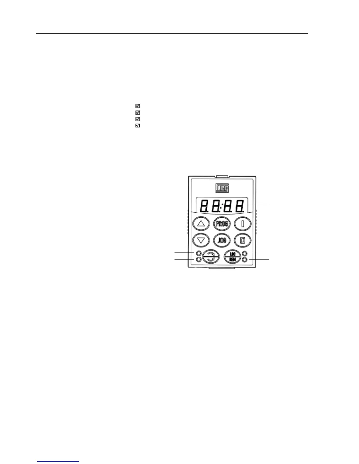
The standard CFW-08 keypad has a LED display with 4 digits of 7
segments, 4 status LEDs and 8 keys. Figure 5.1 shows the front view of
the keypad and indicates the position of the display and the status LEDs.
LED Display
Green Led "Local"
Red Led "Remote"
Led "FWD"
Led "REV"
Figure 5.1 - CFW-08 standard keypad
Functions of the LED Display:
The LED display shows the fault codes and drive status (see Quick
Parameter Reference, Fault and Status), the parameter number and its
value. For units of current, voltage or frequency, the LED display shows
the unit in the right side digit [U = Volts, A = Ampères,
o
= Celsius Degree
(
o
C)]
Functions of the “Local” and “Remote” LEDs:
Inverter in Local Mode:
Green LED ON and red LED OFF.
Inverter in Remote Mode:
Green LED OFF and red LED ON.
Functions of the FWD/REV LEDs - Direction of Rotation
Refer to Figure 5.2
CHAPTER 5