146
CFW-08 OPTIONS AND ACCESSORIES
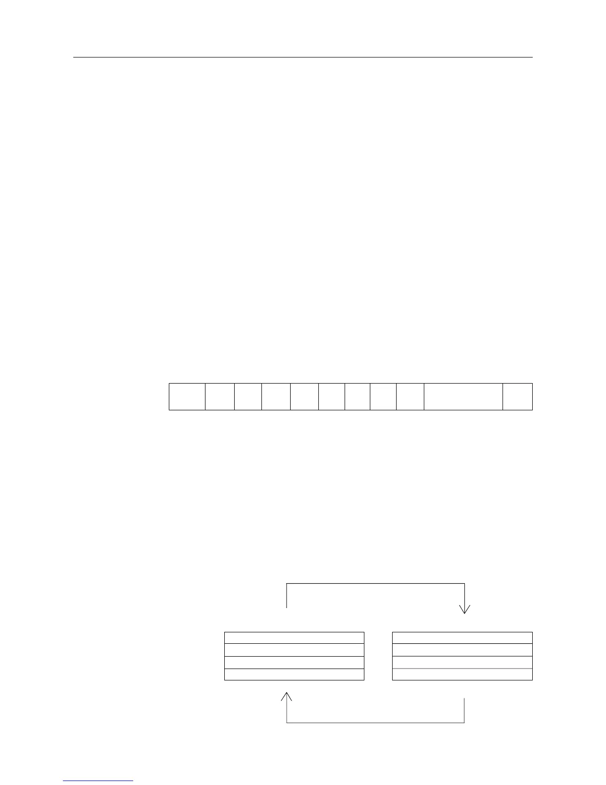
Figure 8.26 - Message Structure
Master Query Message
Address (1 byte)
Function Code (1 byte)
Data (n bytes)
CRC (2 bytes)
Address (1 byte)
Function Code (1 byte)
Data (n bytes)
CRC (2 bytes)
Slave Answer Message
Start B0 B1 B2 B3 B4 B5 B6 B7 Parity or Stop Stop
8.20 MODBUS-RTU
8.20.1 Introduction to
Modbus-RTU Protocol
Modbus protocol has been already developed 1979 firstly. Currently it is a
wide diffused open protocol, used by several manufacturers in different
equipment. The Modbus-RTU communication of the do CFW-08 has been
developed by considering two documents:
1. MODBUS Protocol Reference Guide Rev. J, MODICON, June 1996.
2. MODBUS Application Protocol Specification, MODBUS.ORG,
may 8th 2002.
In these documents are defined the format of the messages used by
these elements that are part of the Modbus network, the services (or
functions) that can be made available via network, and also how these
elements exchange the data on the network.
8.20.1.1 Transmission
Modes
In the RTU mode each transmitted word has 1 start bit, eight data bits, 1
parity bit (optional) and 1 stop bit (2 stop bits, if parity bit is not used).
Thus the bit sequence for the transmission is as follows:
8.20.1.2 Message Structure
In RTU ModeThe Modbus RTU network operates in Master-Slave system
and it can consist of up to 247 slaves but only one Master. The master
always initiates the communication with a question to a slave and the
slave answers the question. Both messages (question and answer) have
the same structure: Address, Function Code, and CRC. Depending on
what is being requested, only the data field has variable length.
Two transmission modes are defined in the protocol definition: ASCII and
RTU. The transmission modes define the form how the message bytes
are transmitted. It is not permitted to use the two transmission modes on
the same network.
In the RTU mode each transmitted word has one start bit, eight data bits,
1 parity bit (optional) and 1 stop bit (2 stop bits, if no parity bit is used).
Thus the bit sequence for the transmission of 1 byte is as follows: