131
CFW-08 OPTIONS AND ACCESSORIES
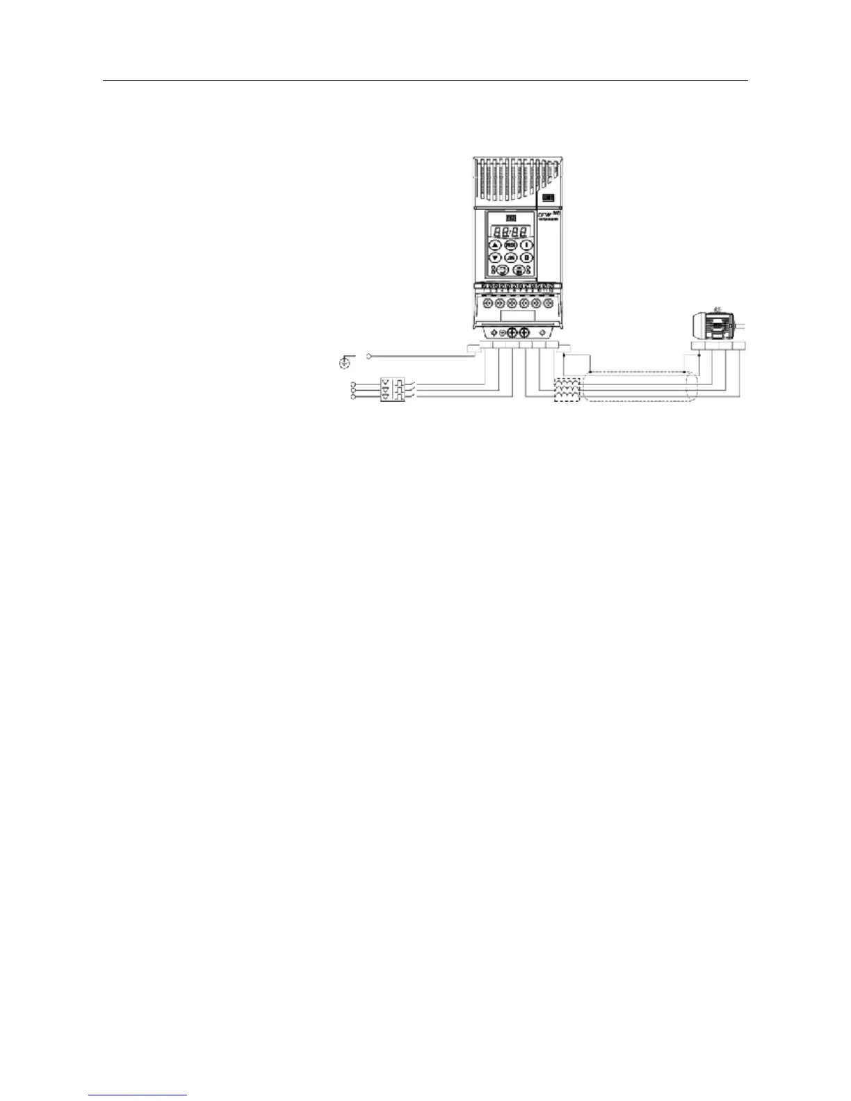
Figure 8.22 - Load Reactor Connection
8.18 DYNAMIC BRAKING
The dynamic braking is used where short deceleration times are required
or where high inertia is present.
For the correct sizing of the braking resistor, application data such as,
deceleration time, load inertia, braking duty cycle must be considered.
In any case, the rms current capacity and the maximum peak current
must be considered.
The maximum peak current defines the minimum permitted ohmic value
for the braking resistor. Refer to table 8.4.
The DC link voltage level for the actuation of the dynamic braking is as
follows:
Inverter supplied with 200...240V: 375Vcc
Inverters supplied with 380...480V: 750Vcc
R
S
T
PE
PE
RSTUVW
U
V
W
8.18.1 Resistor Sizing
The braking torque, that can be obtained through the frequency inverter,
without using the dynamic braking module, varies from 10 to 35% of the
rated motor torque. During the deceleration process, the kinetic energy of
the load is regenerated into the inverter DC link. This energy loads up the
capacitors by increasing the DC link voltage. When this energy is not
fully dissipated, it may generate a DC link overvoltage trip (E01) and
disabling the inverter.
To obtain higher braking torques, the use of dynamic braking is
recommended where the excess of the regenerated energy is dissipated
in a resistor mounted externally to the inverter. The braking resistor is
defined according to the deceleration time, load inertia and resistive torque.
In most cases, a resistor with an ohmic value as indicated on the table
below and a power rating of 20% of the driven motor can be used.
Use wire type or tape type resistors with suitable insulation to withstand
the instantaneous current peaks.
For critical applications with very short braking times, high inertia loads
(ex.: centrifuges) or with very short and frequent duty cycles, contact
WEG to define the most suitable resistor.
PE
DISCONNECTING
SWITCH
PE
LOAD
REACTOR
SHIELD