112
DIAGNOSTICS AND TROUBLESHOOTING
NOTE!
The faults act as follows:
E00 ... E06: switches off the relay that has been programmed to “no
fault”, disables the PWM pulses, displays the fault code on the display
and the “ERROR” LED flashes.
Some data are saved on the EEPROM memory: keypad reference
and EP (electronic potentiometer) (when the function “backup
of the references” at P120 has been enabled), the occurred fault number,
the status of the integrator of the IxT function (overcurrent).
E24: Indicates the fault code on the LED display.
E31: Inverter proceeds to operate normally, but it does not accept
the keypad commands; the fault code is indicated on the LED display.
E41: does not allow inverter operation (it is not possible to enable the
inverter); the fault code is indicated on the LED display and on the
“ERROR” LED.
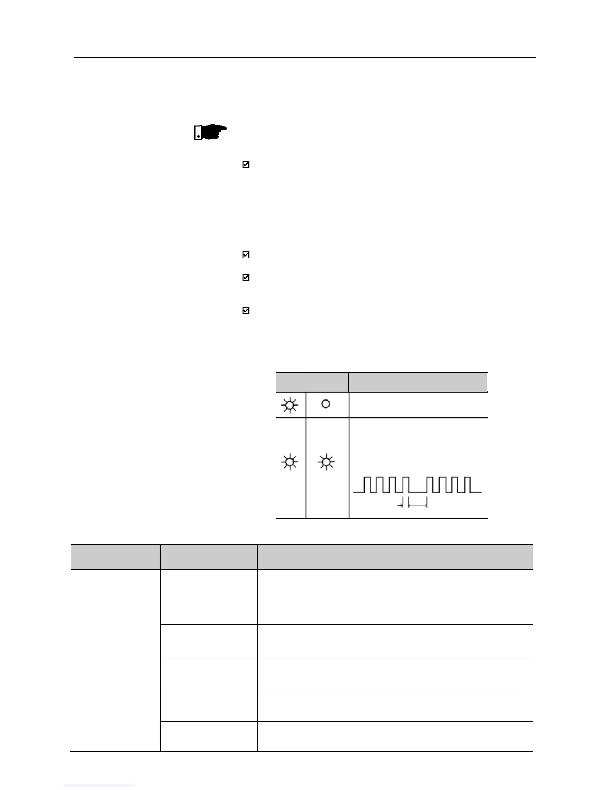
Indication on the Inverter Status LEDs:
7.2 TROUBLESHOOTING
PROBLEM
POINT TO BE
CORRECTIVE ACTION
CHECKED
Motor does not run Incorrect wiring 1.Check the power and the control connections. For example,
the digital inputs DIx programmed for Start/Stop or General Enable
or No External Fault must be connected to GND (pin 5 of the
control connector XC1).
Analog reference 1.Check if the external signal is properly connected.
(if used) 2.Check the status of the speed potentiometer (if used).
Incorrect Programming 1.Check if the parameters are properly programmed for the
application.
Fault 1.Check if the inverter has not been disabled due to detected fault
condition (refer to Table above).
Motor Stall 1.Reduce the motor load.
2.Increase P169 or P136/P137.
(Flashing)
Inverter is powered up and is ready
A fault has been detected.
The Error LED flashes, indicating the
number of the fault code.
Example: E04
0,2s 0,6s
Power
LED
Error LED Description