73
DETAILED PARAMETER DESCRIPTION
Range
[Factory Setting]
Parameter Unit Description / Notes
P023 x.yz
Software Version [ - ]
-
P040 0...P528
Process [ - ]
Variable (PID) 1
P100 0.1...999s
Acceleration [ 5.0s ]
Time #1 0.1s (<100);
1s (>99.9)
P101 0.1...999s
Deceleration [ 10.0s ]
Time #1 0.1s (<100);
1s (>99.9)
P102 0.1...999a
Acceleration [ 5.0s ]
Time #2 0.1s (<100);
1s (>99.9)
P103 0.1...999s
Deceleration [ 10.0s ]
Time #2 0.1s (<100);
1s (>99.9)
Indicates the software version installed in the DSP memory located
on the control board.
Parameter P040, P203, P520 to P528 are only available from the
software version V3.50 on.
Indicates the value of the process variable used as PID feedback,
in percent (%).
The PID function is only available from the software version V3.50
on.
The indication unit can be changed through P528.
See detailed description of the PID regulator in Section 6.3.5 -
Special Function Parameters.
This set of parameters defines the time to accelerate linearly from
zero up to the rated frequency and to decelerate linearly from
the rated frequency down to zero.
The rated frequency is defined by parameter:
- P145 in V/F control (P202=0 ou 1);
- P403 in vector control (P202=2).
When factory setting is used, inverter always follows the time defined
in P100 and P101.
Ramp #2 is used, the the acceleration and deceleration times
follow the values programmed at P102 and P103, use a digital input.
See parameters P263 ... P265.
Depending on the load inertia, too short acceleration times can
disable the inverter due to overcurrent (E00).
Depending on the load inertia, too short deceleration times can
disable the inverter due to overvoltage (E01). For more details,
refer to P151.
6.3.2 Regulation Parameters - P100 ... P199
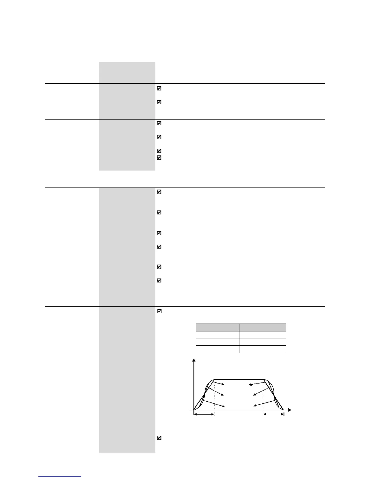
P104 0...2
S Ramp [ 0 - Inactive ]
-
The ramp S reduces mechanical stress during the acceleration and
deceleration of the load.
Figure 6.4 - S or linear ramp
It is recommended to use the S ramp with digital frequency/speed
references.
Accel Time
(P100/102)
Decel Time
(P101/103)
P104
0
1
2
Ramp S
Inactive
50%
100%
Output frequency
(Motor speed)
Linear
t (s)
50% ramp S
100% ramp S