37
INSTALLATION AND CONNECTION
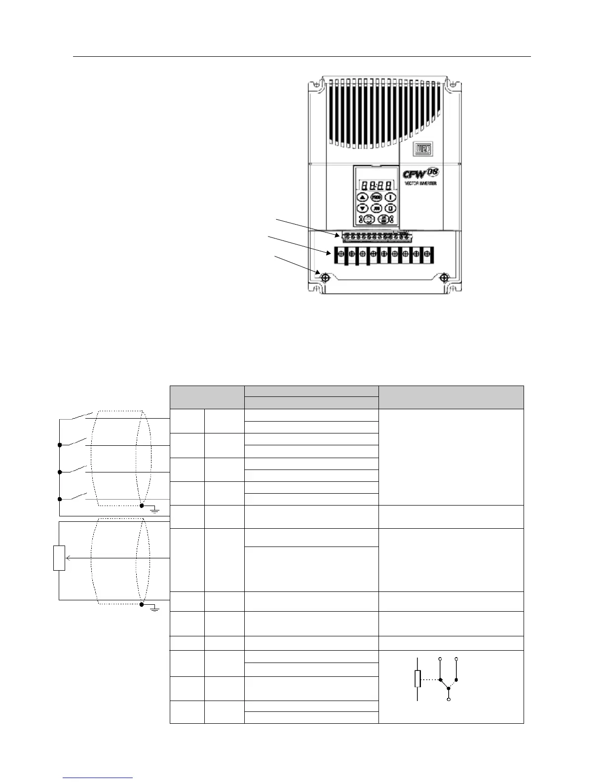
3.2.4 Control
Wiring
The control wiring (analog inputs/outputs, digital inputs and relay outputs
is made on the XC1 connector of control board (see location in Figure 3.7,
Section 3.2.3).
There are two configurations for the control board: standard version
(CFW-08 line) and Plus version (CFW-08 Plus line), as shown below:
Figure 3.8 - XC1 control terminal description (standard control board - CFW-08)
Note: NC = Normally Closed Contact, NO = Normally Open Contact
Figure 3.7 - Location of the power/grounding and control connections
(b) Models 13-16A/380-480V
Control XC1
Power
Grounding
XC1 Terminal
1DI1
2DI2
3DI3
4DI4
5 GND
6 AI1
7 +10V
8
9
10 NC
11 Commom
12 NO
Description
Factory Default Function
Digital Input 1
General Enable (remote mode)
Digital Input 2
FWD / REV (remote mode)
Digital Input 3
Reset
Digital Input 4
Start / Stop (remote mode)
0V Reference
Analog Input 1
Frequency / Speed Reference
(remote mode)
Potentiometer reference
Not used
Not used
Relay Output 1 - NC contact
No Fault
Relay Output 1 - common point
Relay Output 1 - NO contact
No Fault
Specifications
4 isolated digital inputs
Minimum High Level: 10VDC
Maximum Low Level: 3VDC
Input current: -11mA @ 0V
Max. input current: -20 mA
Not connected to PE
0 to 10VDC or 0(4) to 20mA (fig. 3.10).
Impedance: 100kΩ (0...10V input),
500Ω (0/4...20mA input).
Resolution: 7bits.
Max. input voltage: 30 VDC
+10VDC
±
5%, capacity: 2mA
Contact capacity:
0.5A / 250VAC
Relé 1
CW
CCW
≥
5k
Ω
10 12
11