55
START-UP
4.3.2 Start-up
Operation Via Terminals -
Control Mode:
Linear V/F (P202=0)
Connections are according to Figures 3.4 and 3.12.
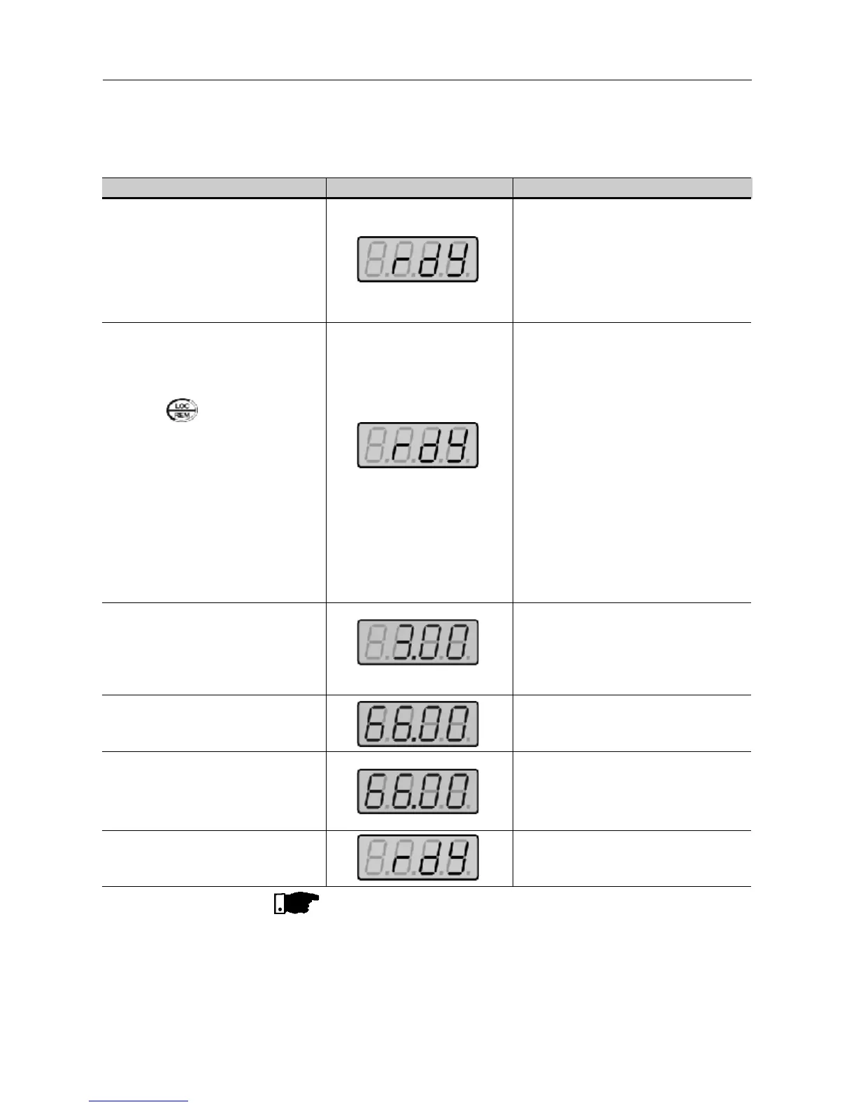
ACTION HMI DISPLAY DESCRIPTION
See Figure 3.12
Switch S1 (FWD / REV)=open
Switch S2 (Reset)=open
Switch S3 (Start/Stop)=open
Potentiometer R1 (Ref.)=totalzly CCW
Power-up inverter
Press the key
This procedure is not necessary when
inverters were delivered dummy panel,
since it will be automatically in remote
mode.
Close S3 – Start/Stop
Turn potentiometer totally CW.
Clse S1 – FWD / REV
Open S3 – Start / Stop
Inverter is ready to be operated.
Led LOCAL switches OFF and led
REMOTE switches ON. Control and
Reference are are switched to REMOTE
(via terminals).
To maintain inverter permanently in
REMOTE mode, set P220 = 1.
Note: If the inverter is switched off and
afterwards switched on, it will now
operate in local mode because P220=2
(factory setting). This setting means that
the local/remote selection source is via
keypad and the default mode (that is the
mode when the inverter is switched on)
is local. For further information see
description of P220 in Chapter 6.
Motor accelerates from 0Hz to 3Hz* (min.
frequency), CW direction
(1)
* 90rpm for 4-pole motor
The frequency reference is given by the
potentiometer R1.
Motor accelerates up to the the maximum
frequency (P134 = 66Hz)
(2)
Motor decelerates
(3)
down to 0 rpm (0Hz),
reverses the direction of rotation (CW ⇒
CWW) accelerating back up to the
maximum frequency (P134 = 66Hz).
Motor decelerates
(3)
down to 0 rpm.
NOTES!
(1) If the direction of roation of the motor rotation is not correct, switch off
the inverter. Wait 10 minutes to allow a complete capacitor discharge
and the swap any two wires at the motor output.
(2) If the acceleration current becomes too high, mainly at low frequencies,
set the torque boost (IxR compensation) at P136.
Increase/decrease the content of P136 gadually until you obtain an
operation with constant current over the entire frequency range.
For the case above, refer to Parameter Description in Chapter 6.
(3) If E01 fault occurs during deceleration, increase the deceleration time
at P101 / P103.