156
CFW-08 OPTIONS AND ACCESSORIES
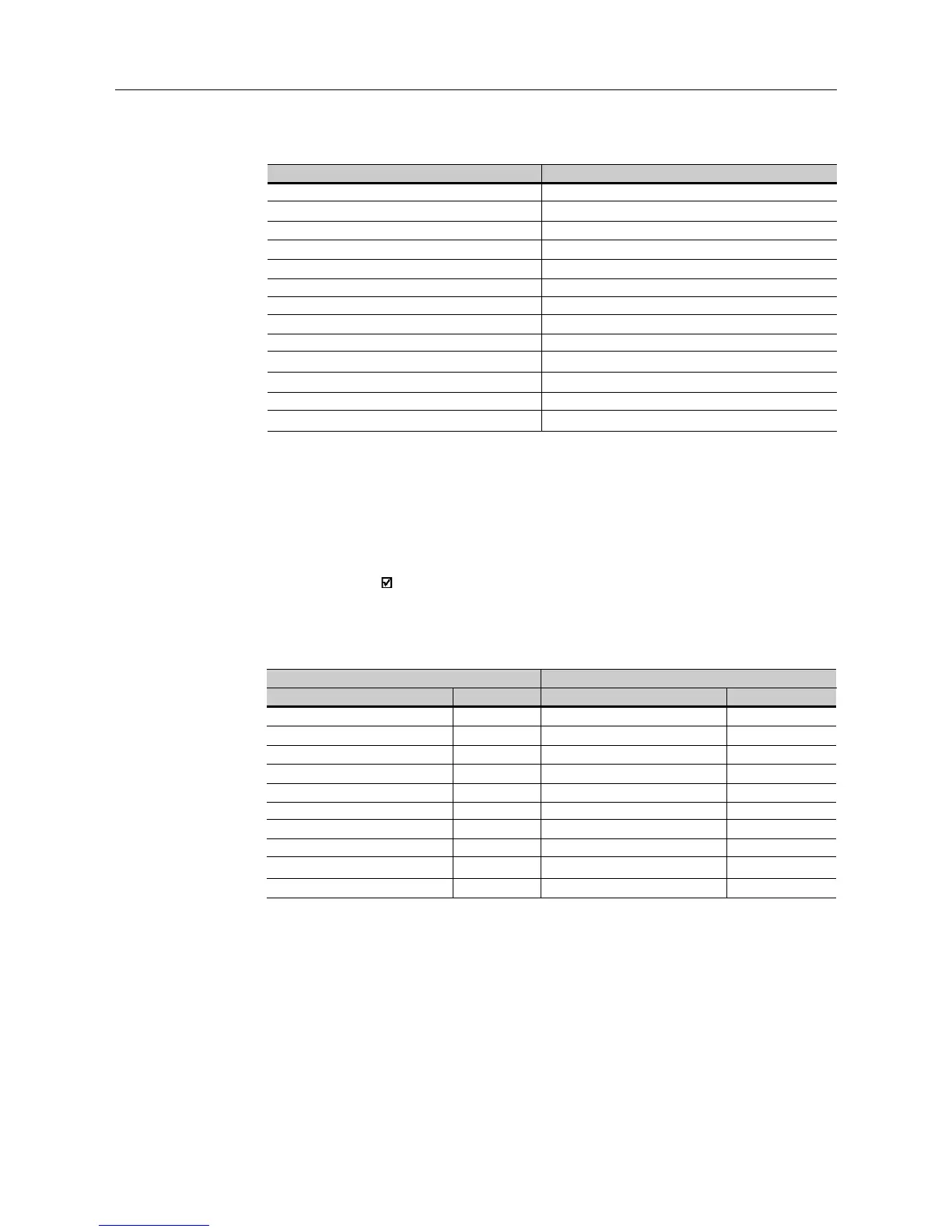
Query (Master)
Slave address
Function
Initial bit address (byte high)
Initial bit address (byte low)
Number of bits (byte high)
Number of bits (byte low)
Byte Count Field (number of data bytes)
Byte 1
Byte 2
Byte 3
etc...
CRC-
CRC+
Response (Slave)
Slave address
Function
Initial bit address (byte high)
Initial bit address (byte low)
Number of bits (byte high)
Number of bits (byte low)
CRC-
CRC+
The value of each bit that is being sent is placed at a position of the data
bytes sent by the master. The first byte, in the bits 0 to 7, receives the 8
first bits by starting from the initial address indicated by the master. The
other bytes (if the number of inscribed bits is higher than 8) remain in
sequence. If the number of inscribed bits is not a multiple of 8, the remaining
bits of the last byte should be filled in with 0 (zero).
Example: command writing for general enabling (bit 100 = 1), general
enabling (bit 101 = 1) and CWW-direction of rotation (bit 102 = 0), for
a CFW-08 at address 1:
Query (Master)
Field Value
Slave address 01h
Function 0Fh
Initial bit (byte high) 00h
Initial bit (byte low) 64h
Number of bits (byte high) 00h
Number of bits (byte low) 03h
Byte Count 01h
Bits Value 03h
CRC- BEh
CRC+ 9Eh
Response (Slave)
Field Value
Slave address 01h
Function 0Fh
Initial bit (byte high) 00h
Initial bit (byte low) 64h
Number of bits (byte high) 00h
Number of bits (byte low) 03h
CRC- 54h
CRC+ 15h
8.20.3.6 Function 16 - Write
Multiple Registers
This function allows writing values to a register group that must be in
numerical sequence. This function can also be used to write a single
register (the values are always hexadecimal values and each field represents
one byte).
As only three bits are written, the master needed only one byte to transmit
the data. The transmitted values are in the three less significant bits of
the byte that contains the value for the bits. The other bits of this byte
remained with the value 0 (zero).