139
CFW-08 OPTIONS AND ACCESSORIES
The messages are processed in the inverter in determined intervals.
Therefore, a pause larger than the sum of the times T
proc
+ T
di
+ T
txi
should be ensured between two messages addressed to the same inver-
ter (refer to section 8.18.6.).
8.19.3.6 Message
Sequence
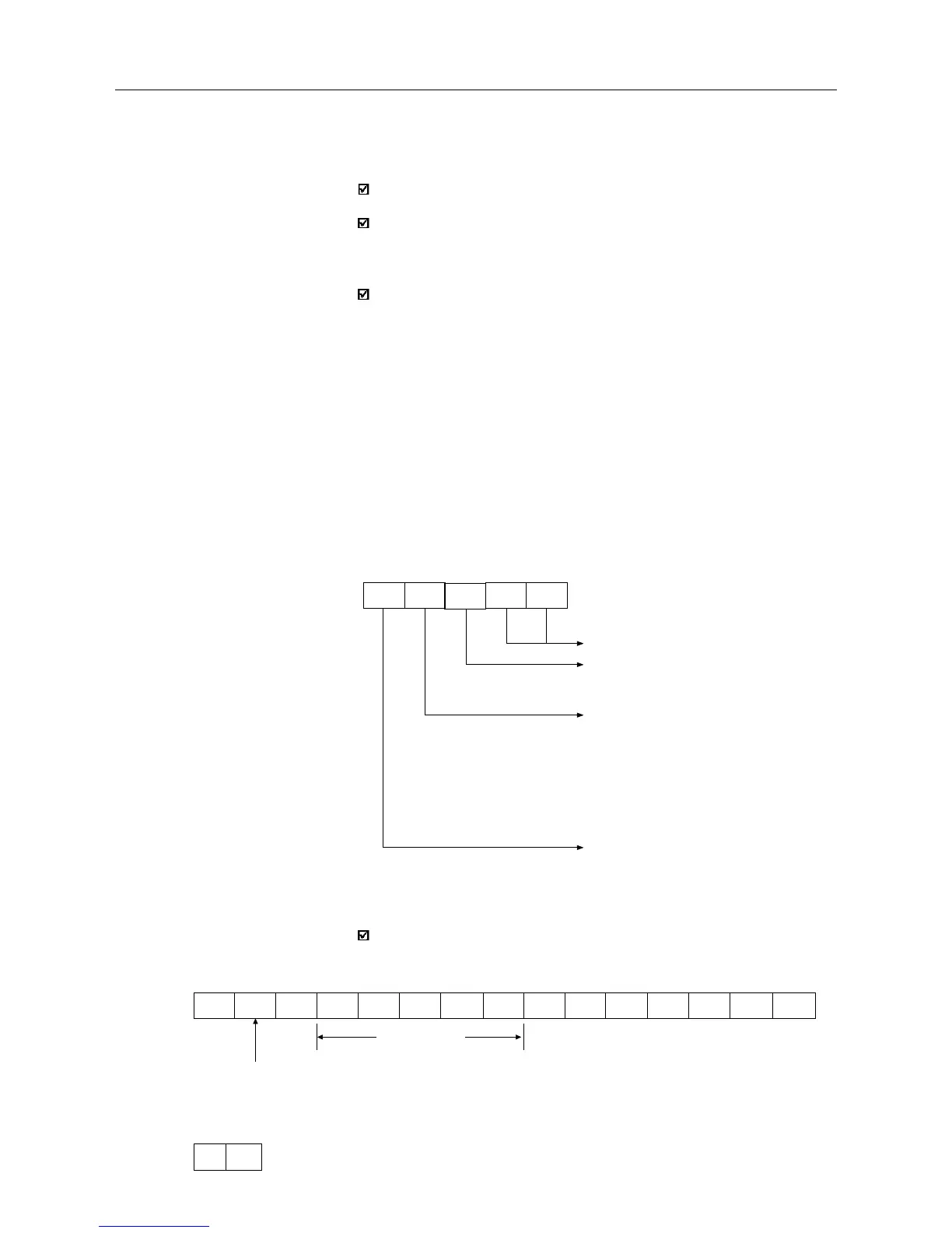
8.19.3.7 Variable Code
The field designated with CODE determines the parameter address and
the basic variables formed by 5 digits (ASCII characters) as follows:
8.19.4 Message Examples
Change of the minimum frequency (P133) to 6.00Hz in the inverter 7.
1) Master:
Fmin
F
min
=258H=600=6.00/0.01
addr. 7
2) Inverter:
G ACK
Writing Message:
no answer: with wrong message structure, control characters
received incorrectly or wrong inverter address;
NAK: CODE corresponding to a non existing variable, wrong BCC
(checksum byte), only reading variable, VAL out of the allowed
range for the respective variable, operation parameter out of the alteration
mode;
ACK: with valid message;
The master should maintain, between two variable transmissions to the
same inverter, a waiting time that is compatible with the used inverter.
CODE
X X X X X
Number of the basic variable or parameter
Equipment number:
"7" = CFW08
"9" = any inverter
Specifier:
0 = basic variables
1 = P000 to P099
2 = P100 to P199
3 = P200 to P299
4 = P300 to P399
5 = P400 to P499
6 = P500 to P599
7 = P600 to P699
Equal to zero (0)
EOT G STX 0 2 7 3 3 = 0H 2H 5H 8H ETX BCC