53
START-UP
4.3 START-UP
4.3.1 Start-up
Operation via Keypad
(HMI)- Type of Control:
Linear V/F(P202=0)
Connections according to Figure 3.4.
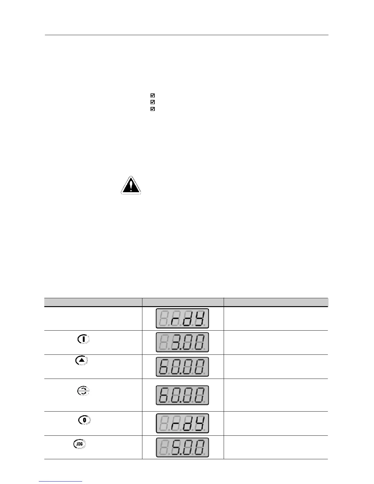
ACTION HMI DISPLAY DESCRIPTION
Power-up the inverter
Press the key
Press the key and hold it
depressed until 60 Hz is reached
Press the key
Press the key
Press the key and hold it
depressed
Inverter is ready to be operated
Motor accelerates from 0Hz to 3Hz*
(min. frequency), in the forward (CW) direction
of rotation
(1)
* 90rpm for 4 pole motor.
Motor accelerates up to 60Hz*
(2)
* 1800rpm for 4-pole motor
Motor decelerates
(3)
down to 0 rpm and
then reverses the direction of rotation
CW⇒CWW accelerating back to 60Hz
Motor decelerates down to 0 rpm
Motor accelerates up to JOG frequency
given by P122. Ex: P122 = 5.00Hz.
Reverse (CCW)
DANGER!
Even after the AC power supply has been disconnected, high voltages
may be still present. Wait at least 10 minutes after powering down to
allow full discharge of the capacitors.
The sequence below is valid for the connection 1 (refer to Section 3.2.5).
Inverter must be already installed and powered up according to Chapter 3
and Section 4.2.
This Section describes start-up procedures when operating via the keypad
(HMI). Two types of control will be considered:
V/F and Vetor Control
The V/F control is recommended in the following cases:
several motors driven by the same inverter;
rated current of the motor is lower than 1/3 of rated inverter current
for test purposes, inverter is start-up without load.
The V/F control can also be used in applications that do not require fast
dynamic responses, accurate speed regulations or high starting torque
(speed error will be a function of the motor slip); when you program
parameter P138 - rated slip - you can obtain a speed accuracy of 1%.
For the most applications, we recommend the vector control mode, that
permits a higher speed control accuracy (typical 0.5%), higher starting
torque and a faster dynamic response.