43
INSTALLATION AND CONNECTION
3.3 European EMC Directive -
Requirements for
Conforming Installations
The CFW-08 inverter series was designed considering safety and EMC
(ElectroMagnetic Compatibility) aspects.
The CFW-08 units do not have an intrinsic function until connected with
other components (e. g. a motor). Therefore, the basic product is not CE
marked for compliance with the EMC Directive. The end user takes personal
responsibility for the EMC compliance of the whole installation. However,
when installed according to the recommendations described in the product
manual and including the recommended filters and EMC measures the
CFW-08 fulfill all requirements of the EMC Directive (89/336/EEC) as
defined by the EMC Product Standard for Adjustable Speed Electrical
Power Drive Systems EN61800-3.
Compliance of the CFW-08 series is based on the testing of the
representative models. A Technical Construction File was checked and
approved by a Competent Body.
3.3.1 Installation
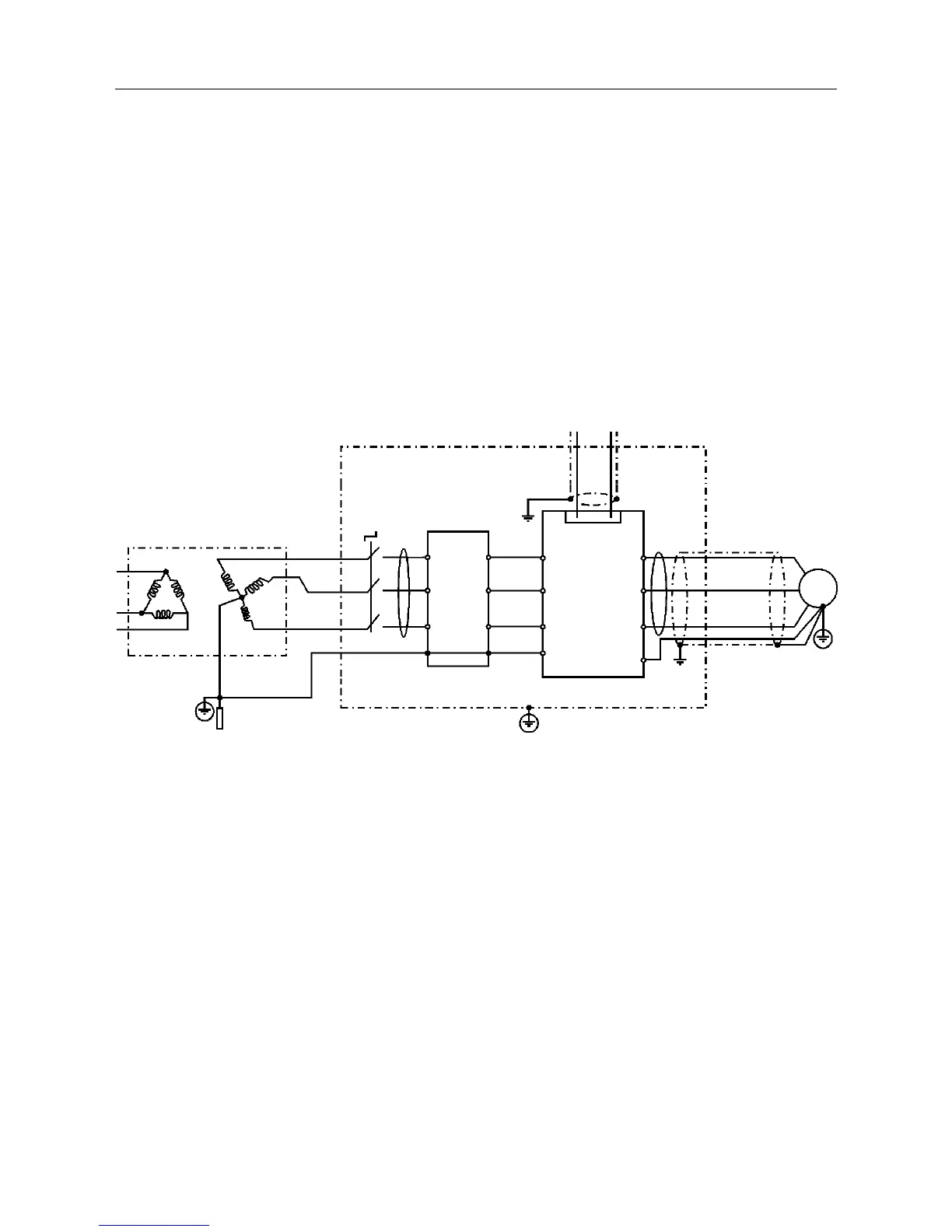
Figure 3.15 below shows the EMC filters connection.
Figure 3.15 - EMC filters connection - general condition
The following items are required in order to have a conforming installation:
1) The motor cable must be armored, flexible armored or installed inside a
metallic conduit or trunking with equivalent attenuation. Ground the screen/
metallic conduit at both ends (inverter and motor).
2) Control (I/O) and signal wiring must be shielded or installed inside a
metallic conduit or trunking with equivalent attenuation.
3) The inverter and the external filter must be mounted on a common metallic
back plate with a positive electrical bond and in close proximity to one
another. Ensure that a good electrical connection is made between the
heatsink (inverter) / frame (external filter) and the back plate.
4) The length of the wiring between filter and inverter must be kept as short
as possible.
5) The cable’s shielding must be solidly connected to the common back
plate, using a metal bracket.
6) Grounding as recommended in this manual.
7) Use short and thick earthing cable to earth the external filter or inverter.
When an external filter is used, only use an earth cable at filter input -
the inverter earth connection is done by the metallic back plate.
8) Earth the back plate using a braid, as short as possible. Flat conductors
(e.g. braids or brackets) have lower impedance at high frequencies.
9) Use cable glands whenever possible.
Output CM
Choke
Transformer
Ground Rod/Grid or
Building Steel
Structure
Metallic Cabinet (when required)
Protective Grounding - PE
Motor
PE
CFW - 08
L2/N
L1/L
L3
E
PE
XC1 1...12
U
Input CM
Choke
Controling and Signal Wiring
V
W
PE
L1/L
L2/N
L3
External
Input RFI
Filter
L2
L1
L3
E
Obs.: Single-phase input inverters use single-phase filters and only L1/L and L2/N are used.