145
CFW-08 OPTIONS AND ACCESSORIES
8.19.7 Physical
Connection
RS-232 and RS-485
Note:
The wiring of the RS-232 must be laid separately from the power cables
and the control wiring in 110/220V.
NOTE!
You can not use RS-232 and RS-485 simultaneously.
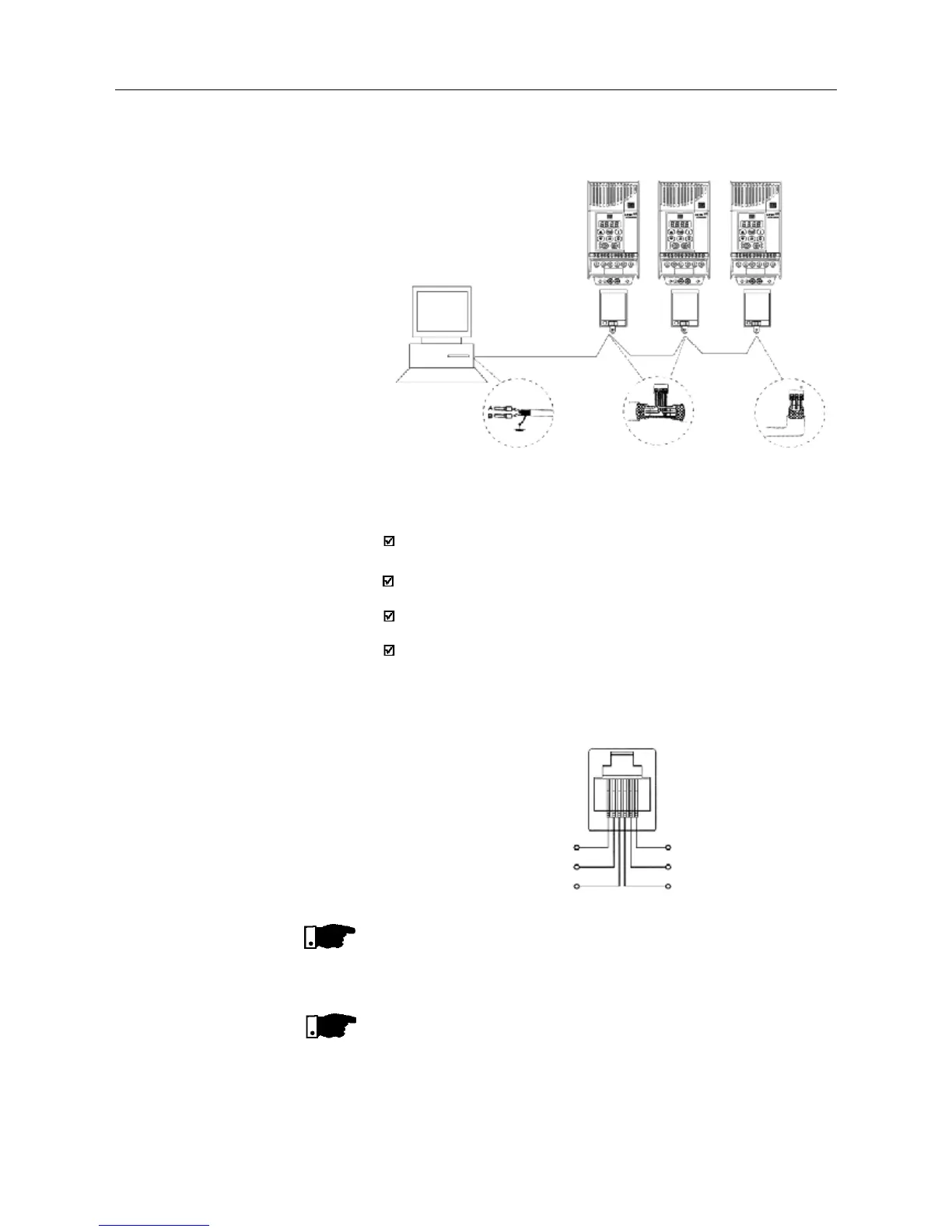
Figure 8.24 - CFW-08 network connection through RS-485 serial interface
6
5
4
1
2
3
TX
0V
RX
+5V
RTS
0V
Figure 8.25 - Description of the XC8 (RJ-6) connector
Network
Master
(PC, PLC)
RS-485
MIW-02
MIW-02 MIW-02
RS-232
RS-485
CFW-08
CFW-08
CFW-08
BCable
shielding
RS-232
RS-485
A B
RS-485
XC29
A B
RS-485
XC29
RS-232
RS-485
Ω
Notes:
LINE TERMINATION: connect the termination resistors at the ends of
the line.
LINE TERMINATION: include line termination (120 ) at the ends, and
only at the line ends.
GROUNDING OF THE CABLE SHIELD: connect the shielding to the
equipment frame (suitable grounding);
RECOMMENDED CABLE: for balanced shielding.
Ex.: AFS series, manufacturer KMP.
Figure below shows the pin position of the XC8 connector of the KCS-
CFW08-S module.