35
INSTALLATION AND CONNECTION
NOTE!
Supply line capacity:
The CFW-08 is suitable for use in circuits capable of supplying not more
than symmetrical 30.000Arms (240/480V).
The CFW-08 can be installed on power supplies with a higher fault level if
an adequate protection is provided by fuses or circuit breaker.
3.2.2 Power Terminals
Description of the power terminals:
L/L1, N/L2 and L3 (R, S and T): AC supply line
200-240 V models (except 7.0A and 16A) can be opeated
with two phases (single-phase operation) without current derating. In
this case, the AC supply can be connected to any 2 of the 3 input
terminals.
U, V and W: Motor connection.
-UD: Negative pole of the DC link circuit.
Not available on the models 1,6-2,6-4,0-7,0A/200-240V and on the
models 1.0-1.6-2.6-4.0A/380-480V. This pole is used when inverter
shall be supplied with DC voltage (jointly with the +UD terminal).
To avoid wrong connection of the braking resistor (mounted outside
the inverter), inverter is supplied with a rubber plug on this terminal
that must be removed when the use of the -UD terminal is required.
BR: Connection for Dynamic Braking Models (DB).
Not available on types 1.6-2.6-4.0-7.0A/200-240V and on models
1.0-1.6-2.6-4.0A/380-480V.
+UD: Positive pole of the DC link ciruit.
Not available on models 1.6-2.6-4.0-7.0A/200-240V and on models
1.0-1.6-2.6-4.0A/380-480V. This terminal is used to connect the
dynamic braking (DB) (jointly with the BR terminal) or when inverter
shall be supplied with DC voltage (jointly with the -UD terminal).
NOTE!
The wire sizing indicated in Table 3.3 are reference values only. The exact
wire sizing, depends on the installation conditions and the maximum
acceptable line voltage drop.
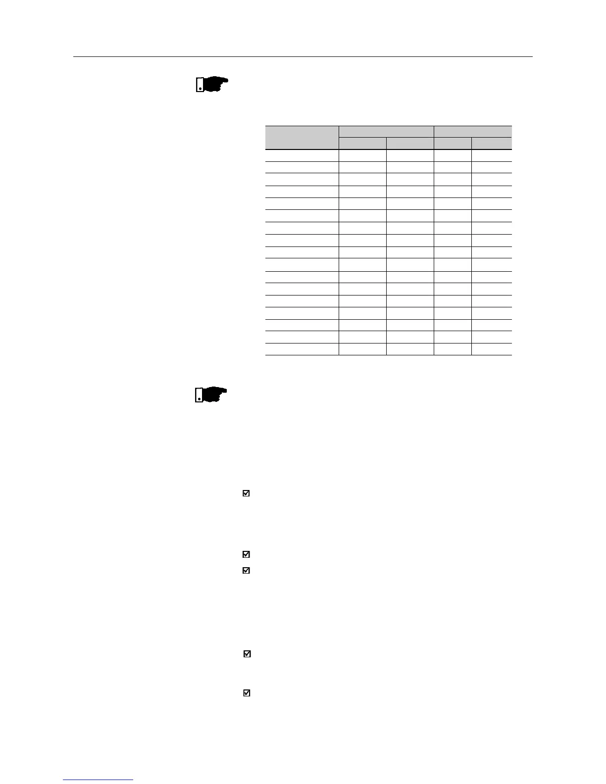
Inverter Model
1.6A / 200-240V
2.6A / 200-240V
4.0A / 200-240V
7.0A / 200-240V
7.3A / 200-240V
10.0A / 200-240V
16.0A / 200-240V
1.0A / 380-480V
1.6A / 380-480V
2.6A / 380-480V
2.7A / 380-480V
4.0A / 380-480V
4.3A / 380-480V
6.5A / 380-480V
10.0A / 380-480V
13.0A / 380-480V
16.0A / 380-480V
Grounding Wiring
N.m Lbf.in
0.4 3.5
0.4 3.5
0.4 3.5
0.4 3.5
0.4 3.5
0.4 3.5
0.4 3.5
0.4 3.5
0.4 3.5
0.4 3.5
0.4 3.5
0.4 3.5
0.4 3.5
0.4 3.5
0.4 3.5
0.4 3.5
0.4 3.5
Power Cables
N.m Lbf.in
1.0 8.68
1.0 8.68
10 8.68
1.0 8.68
1.76 15.62
1.76 15.62
1.76 15.62
1.2 100
1.2 10.0
1.2 10.0
1.76 15.62
1.2 10.0
1.76 15.62
1.76 15.62
1.76 15.62
1.76 15.62
1.76 15.62
Table 3.4 - Recommended tightening torque for power and grounding
connections