34
INSTALLATION AND CONNECTION
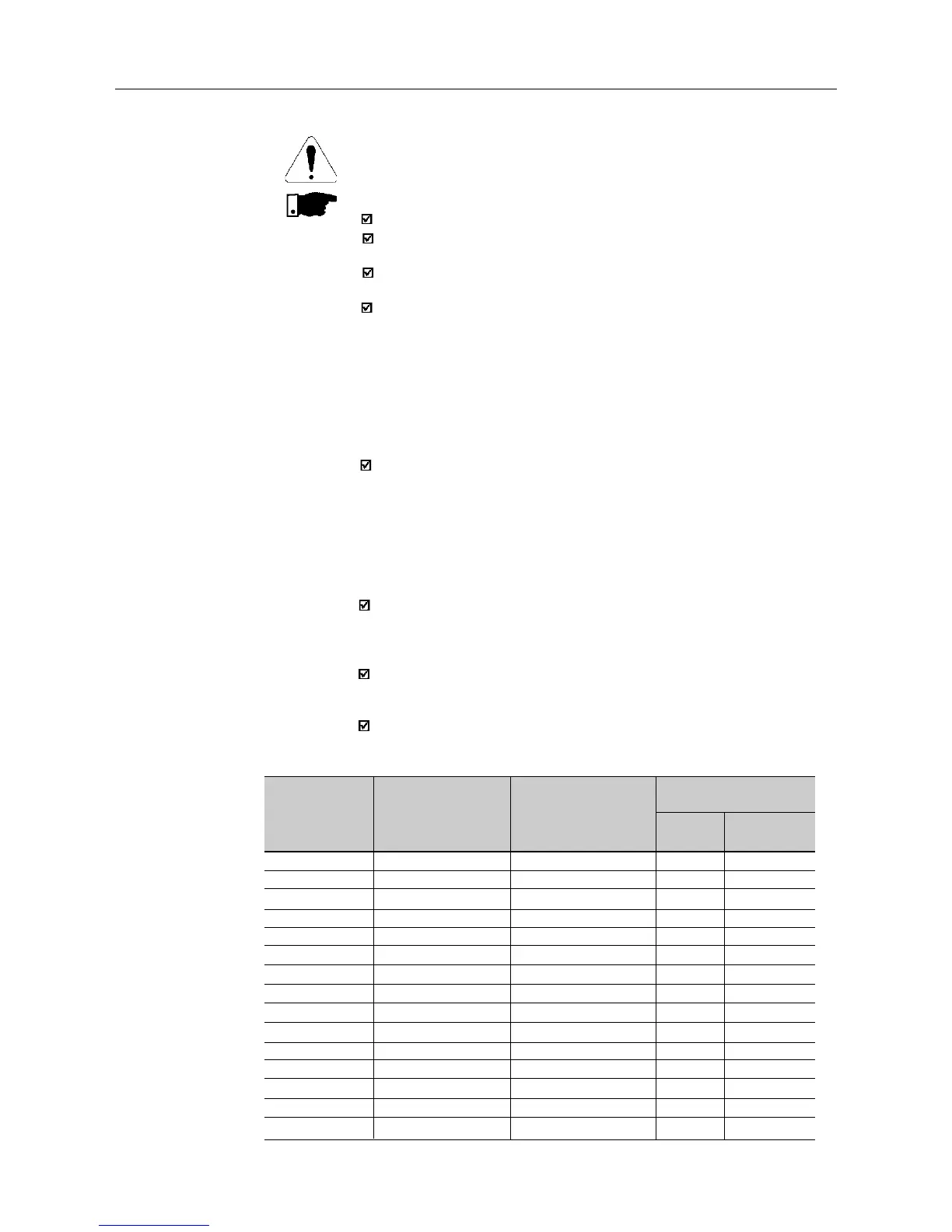
Table 3.3 - Recommended wiring and circuit-breakers - use 70ºC copper wires only
Amp
Rating
[ A ]
1.0
1.6 (200-240V)
1.6 (380-480V)
2.6 (200-240V)
2.6 (380-480V)
2.7
4.0 (200-240V)
4.0 (380-480V)
4.3
6.5
7.0
7.3
10.0
13.0
16.0
Power Cables
[ mm
2
]
1.5
1.5
1.5
1.5
1.5
1.5
1.5
1.5
1.5
2.5
2.5
2.5
2.5
2.5
2.5
Grounding Cables
[ mm
2
]
2.5
2.5
2.5
2.5
2.5
2.5
2.5
2.5
2.5
4.0
4.0
4.0
4.0
4.0
4.0
Current
[ A ]
4
10
4
10
6
6
15
10
10
15
10
20
30
30
35
WEG
Model
DMW25-4
DMW25-6,3
DMW25-4
DMW25-10
DMW25-6.3
DMW25-6.3
DMW25-16
DMW25-10
DMW25-10
DMW25-16
DMW25-10
DMW25-20
DW125H-32
DW125H-25
DW125H-32
Circuit-Breaker
ATTENTION!
The AC input for the inverter must have a grounded neutral conductor.
NOTE!
The AC input voltage must be compatible with the inverter rated voltage.
The requirements for use of line reactors depends on several application
factors. Refer to Section 8.15.
Capacitors for power factor correction are not required at the input
(L/L1, N/L2, L3 or R, S, T) and they must not be connected at the
output (U, V and W).
When inverters with dynamic braking (DB) are used, the DB resistor
shall be mounted externally. Figure 8.21 shows how to connect the
braking resistor. Size it according to the application, not exceeding
the maximum current of the braking circuit. For the connection between
inverter and the braking resistor, use twisted cable. Provide physical
separation between this cable and the signal and control cables. When
the DB resistor is mounted inside the panel, consider watt loss generated
when the enclosure size and required ventilation are calculated.
When electromagnetic interference (EMI), generated by the inverter,
interfers in the performance of other equipment, use shielded wires, or
install the motor wires in metallic conduits.Connect one end of the
shielding to the inverter grounding point and the other end to the motor
frame. Always ground the motor frame. Ground the motor in the panel
where the inverter is installed or ground it to the inverter. The inverter
output wiring must be laid separately from the input wiring as well as
from the control and signal cables.
The inverter is provided with electronic protection against motor overload.
This protection must be set according to the specific motor. When the
same inverter drives several motors, use individual overload realays for
each motor. Maintain the electrical continuity of the motor cable shield.
If a disconnect switch or a contactor is inserted in the motor supply
line, do not operate them with motor running or when inverter is enabled.
Maintain the electrical continuity of the motor cable shield.
Use wire sizing and circuit breakers as recommended in Table 3.3.
Tightening torque is as indicated in Table 3.4. Use (70ºC) copper wires only.